AVR-CAN hardware for CAN-data Capture

My Nissan Leaf Forum

Help Support My Nissan Leaf Forum:

This site may earn a commission from merchant affiliate links, including eBay, Amazon, and others.
For now (needs more testing), I am using the SAME firmware for CAN-Capture and for the SOC-Meter.

Make a hole and plug one RS232-to-USB adapter's male 9-pin "D" connector into the SOC-Meter and it will also send the EV (or CAR, as selected) buss messages to the PC at 115.2 k-baud.

Use our Windows CAN-Do program to capture, time stamp, log, and examine the data.
 
GroundLoop said:
The AV-CAN, well, save your AT90CAN, I say.. :)
As far as I can tell, it's just the "multifunction" switch. Anyone find reason to poke there?
To override the Carwings nag message when the car starts up, I suppose. You could send a button press, which dismisses it.
 
davewill said:
GroundLoop said:
The AV-CAN, well, save your AT90CAN, I say.. :)
As far as I can tell, it's just the "multifunction" switch. Anyone find reason to poke there?
To override the Carwings nag message when the car starts up, I suppose. You could send a button press, which dismisses it.

Now THAT would be an extremely good feature to have. It annoys the %#$# out of me so badly, half the time I just leave it on the screen for the whole trip (I tend to drive the car several times a day for very short trips).
 
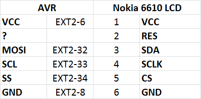
Can anyone tell me waht the ports on AVR-CAN are for the SPI output ? Particularly the "Reset" pin.

I'm now trying out the graphic LCD (Nokia 6610 compatible) with the avr-can.
 
This is what I think it is ...

nokiaavrpins.png


BTW, here is a similar LCD at SparkFun and a ton of related examples. Not sure what I'll use.

http://www.sparkfun.com/products/569
 
Is this the Reset (active low) going to the uP itself?
That is on the schematic of the AVR-CAN board as EXT1-7.

The +5 and Gnd are OK, but I have no idea what 3 signal pins are used by your software.

At least get the AVR-CAN board schematic from Mouser, SparkFun, or Olimex.
 
garygid said:
Is this the Reset (active low) going to the uP itself?
I think reset could be any data pin we can control. Cathy uses PA7 here ...

http://www.idleloop.com/robotics/ColorLCD/

The rest of the pins I think are correct.
 
Oh, this SPI-Reset is an SPI output from the uP to the Display device?

I have not yet read about SPI signaling.

If this is done in software, and not hardware-aided (like the 2 UARTs in the AT90CAN128 uP), one might have to disable the logging code, or do the SPI communication in an interrupt or in the wait-for-CAN-message loop.
 
garygid said:
Oh, this SPI-Reset is an SPI output from the uP to the Display device?

I have not yet read about SPI signaling.

If this is done in software, and not hardware-aided (like the 2 UARTs in the AT90CAN128 uP), one might have to disable the logging code, or do the SPI communication in an interrupt or in the wait-for-CAN-message loop.
SPI itself doesn't involve a Reset - but this LCD needs one. It also has a 9th bit quirk - 9th bit is used to distinguish between data & control.

My plan is to write to LCD at the same place you write to LED now. I should be able to test this out over the weekend.
 
garygid said:
Great, I look forward to seeing your results.
Reset cursor, write 4 characters?
No I was going to write a bunch of stuff - but no go yet.

The problem is either the samples are not for atmega128 or they are not for Phillips LCD I've (there are also Epson ones floating around). I also can't use in debug mode since timing will be wrong.

Ofcourse I'm absolutely new to AVR programming ...
 
CORRECTION NOTE on AVR-CAN Board:

It was recently brought to my attention that the AVR-CAN development
board (that we have been using on the LEAF with no apparent problems
for 3 years) really has two options set that I did not expect from the
schematic, and somehow overlooked.

Apparently they are not critical in the LEAF, but they might affect
other vehicles. So, this Correction Note...

1. The AVR-CAN board, as delivered from the factory, has the CAN_T
solder jumper factory-installed. For our application (passive listening
to an existing CAN bus), this jumper should be removed, to remove the
extra load of this added Termination resistor from impacting
the existing CAN bus voltage levels and operation.

Is it critical as we use it in the LEAF?
Well, apparently not, since the SOC/GID-Meters are working.

However, this jumper was intended to be open, as shown on the schematic.
I just looked at my early (older) AVR-CAN board (in my original GID-Meter),
and it has this jumper. I removed it, and it still seems to work well.

This CAN_T solder jumper is on the top (visible) side of the board when
the back cover is removed from the GID-Meter. With all power and external
connections removed, a quick swipe of an appropriately hot, small tip
soldering iron should remove the solder bridge between the two pads
on the circuit board. Notice the two "open jumper" CAN_D pads next to it.
It is not necessary to renove all the solder, just let the solder "ball up"
on the two pads, but make sure that the solder "bridge" between the
two pads is gone.

2. The 10k resistor R12 on pin 8 (RS) of the CAN Transceiver chip is wired
to ground, which enables the Transmitter function of the chip. However,
I mistakenly thought it went "up to 5v", which would have inhibited
transmission of CAN Messages, which is what I intended.

Since our GID-Meter firmware does not transmit any CAN messages,
it appears to work OK, but while Receiving a Message, we might be
producing an ACK (Acknowledgement) bit, and I did not intend
our "passive sniffer" to create ACK bits. I need to investigate further.

However, our ACK bits, if any, appear to be harmless, at least so far
in the LEAF. The firmware might be set to not produce ACK bits,
but I do not yet know what it does. Again, more investigation needed.

Cheers, Gary
 
Back
Top