Converting the stock EVSE to an OpenEVSE unit

My Nissan Leaf Forum

Help Support My Nissan Leaf Forum:

This site may earn a commission from merchant affiliate links, including eBay, Amazon, and others.

GlennD

Well-known member
Joined
Dec 18, 2011
Messages
1,493
Location
Anaheim
Stock Nissan 2011, 2012 EVSE to OpenEVSE

After the conversion the EVSE is dual voltage and may be used on a 120V GFCI outlet.

Any modification voids the UL approval. IF THIS MATTERS TO YOU DON'T DO IT!

The OPenEVSE Plus must be modified. IF THIS MATTERS TO YOU DON'T DO IT!

You will be working with 120V and 240V. IF THIS MATTERS TO YOU DON'T DO IT!

The OpenEVSE is a well tested device that completely supports the J1772 standard. With Mwalch's mod if can be used with 120V GFCI outlets.

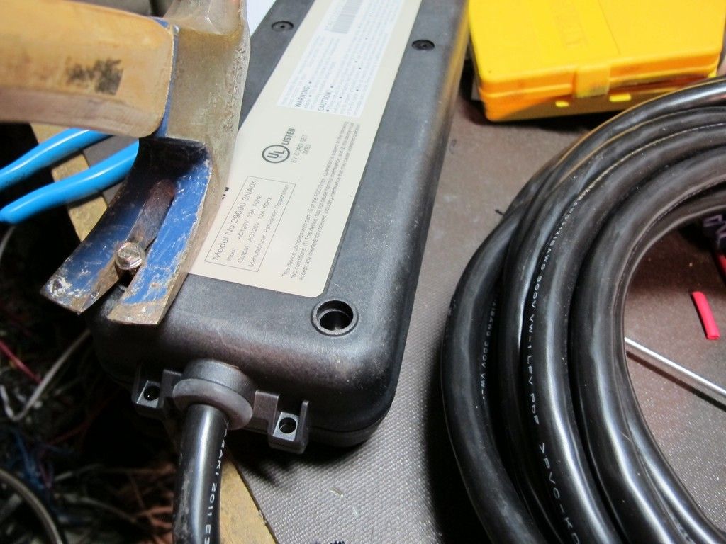
Drill 6 small holes into the center of the hole plugs. Half insert a self tapping or wood screw into each hole and pull them out with a claw hammer. The screws are Torx 15 and require a real driver since the hole will not fit a bit.

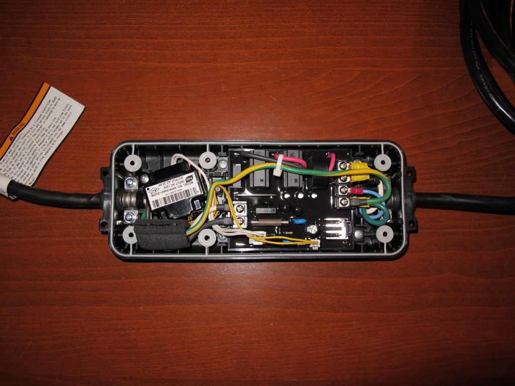
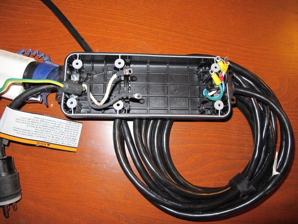
Gut the EVSE since everything is potted and it is not reusable. We only use the cables and case.


I HAVE FOUND THAT REPLACING THE 22k RESISTORS TO 39K IS ALL THAT IS REQUIRED. NO NEED FOR THE MODIFICATIONS EXCEPT REMOTING THE LED.

We need to modify the OpenEVSE Plus. No traces are cut so it can be reversed.
Remove the MID400's and carefully bend up the pin 3's. Use great care since IC pins like to bend only once. If you screw up Digikey has the chips in stock. Reinstall and connect the pins together.

This is Mwalch's mod made made complicated since the input grounds are not seperate like they are on the DIY boards.

I chose to remote the LED so a ground and 3 LED enable wires are connected to the dropping resistors. While testing I found I had to remove the board LEDs. They did not like sharing the dropping resistors.

Since I was adding wires to the underside I brought out 12V, Ground, and the relay coil.


Use the EVSE tray for a template and cut a scrap of aluminum to fit. Mine fits but it is not pretty.
Recess the relay for clearance and mount the OpenEVSE and the fuse holder. Install an 8-32 screw for a ground point.

Wire everything per the schematic on the OpenEVSE site. Wire the switch, relay, and warning led per the mod schematic.

This is a general guide, not a step by step guide. I assume you have an electronic background.
I used an L6-20 plug so that the widely available Ingeneer' adapters will work.


Some random thoughts:

I chose to use LEDs to maintain the stock look. If the fuse holder is moved to a plate where the power transformer was then there is room to mount a display.

If you do not have electrical skills then Ingineer offers a well tested conversion. It is not UL approved but it has stood the test of time. Phil fully stands behind it.
 
Looks great.

I am working on small remote LED board that will be avaliable soon. It works over i2c and uses the same chip and code and the RGB LCD.

I like the mod to disable the ground checks. I may have to all a header/jumper in on a future revision to make it easier.
 
The 120V GFCI mod seems to work well. In my 1976 Townhouse the only GFCI outlets are ones I added. The one in the bathroom that I added 18 years ago has red and black buttons. It does trip and requires the disable. One in the kitchen that I added several years ago with white buttons does not care. It was a cheap Home Depot unit.


I tested my EVSE using Chris Howell's simulator. The one I usually use is mounted in the black box but it is the stock unit with switches. The EVSE passed all tests.

I then checked the GFCI circuit. I use 2 10K power resistors that were in my junk box. The GFCI is set for around 20ma. One resistor draws around 12ma and should not cause a fault touching the output pins to ground. Both resistors together will draw around 24ma, The EVSE passed both tests. It tripped with both and did not with only one.
 
Chris, I thought about using a spare board with no display and a LED instead but I had no common positive ones on hand.

Your idea is a good one. Soldering to the resistors is a challenge and connecting to the LED pads would be nearly impossible.
 
Somehow my 4TH part got messed up and had no txt and a duplicate closeup.

I recovered my original txt and I am going to repost it here.

Some random thoughts:

I chose to use the the existing LED holes to maintain a stock look. It is nearly as water resistant as the stock unit. No unit is waterproof.

If you move the fuse holder to a plate where the original transformer was mounted then there is room to mount a display.

OpenEVSE supports both the color RGB display and the monochrome backpack. For outdoors using the yellow display would be better since it changes to reflective under bright conditions.

The OpenEVSE board fully supports mutiple currents. Do not set L2 higher than 20A. If you set it for 80A then my Leaf would still draw 16A since the charger sets the current but plugging in a Tesla would burn up the unit.

With a display and button you could use Goldserve's real time timer. If you do, reward his work.

If I was to do it again, I would increase the separation with the fuse holder.I would move it about a quarter inch. That would still allow room for the GFCI coil but it would be easier to access the terminals.

For those of you with no electronic skills, Ingeneer sells a reliable upgrade. It is not UL approved but it has been time tested and Phil stands behind it.
 
It was a perfectly working unit. I have the guts here if anyone needs to repair a failed unit.

The whole point was to convert the unit to be a universal 120-240V, 16-20A unit at a relatively low cost.

I had all of the parts on hand and it was a fun project.

The OpenEVSE Plus module is so small it really could fit anywhere. The biggest challenge was fitting in the relay. It just fit.
 
I was pursuing the OpenEVSE web site and I noticed Greg changed the L sense resistors from the recommended 22K to 27K on his latest DIY ver4 board. That got me thinking and I downloaded the mid400 data sheet.

There is a graph that shows resistance vs voltage. The 22K triggers at around 50VAC. Since the power block is from 100V and up it seems overkill. From the chart 100VAC requires a resistor just larger than 40K. I replaced the resistors with 39K 1W flameproof resistors. This works fine and my GFCI no longer trips.

I removed my earlier mods since they are not required. Just changing the resistor values fixes the GFCI problem.
 
How long did it take you to do the conversion, including planning and ordering parts, etc, refinement. Realistically of course:) What is the total parts cost, excluding the EVSE? Roughly.

Thnaks
 
I had the parts on hand. I built the unit on a Saturday.

OpenEVSE Plus $160. Relay $20. GFCI coil $15. Fuse holder and fuses $8. L620P $12 (Ebay). Misc parts $10.

I cut the mounting plate and moved the parts around until I was satisfied. I have had a lot of building experience over the years.
 
EVDRIVER said:
How long did it take you to do the conversion, including planning and ordering parts, etc, refinement. Realistically of course:) What is the total parts cost, excluding the EVSE? Roughly.
Why are you always out to bash anyone's work besides Phil's - especially in an underhanded way like this or a sarcastic way like that? It's very tiresome. We get it. You're an old curmudgeon. If you don't like what someone is doing/saying - just stay out of it instead of spreading negativity around. Or at least try to express your views in a positive manner.

Great job, Glenn - and well documented!
 
Yes, the MOV's are for surge protection. I had them on hand so I used them. on the other 6 units that I have constructed I did not. They just add a little more surge protection. The EVSE works fine without them but every little thing helps.

Just put them after the fuses since the usual MOV failure is a short!
 
drees said:
EVDRIVER said:
We get it. You're an old curmudgeon. If you don't like what someone is doing/saying - just stay out of it instead of spreading negativity around. Or at least try to express your views in a positive manner.

Great job, Glenn - and well documented!


First off I was not bashing anyone and there is not a single negative comment in that post. I wanted to know how much it cost and the time required because I was thinking of doing this with a bad unit I was given and did not want to research the time involved. Speaking of bashing, what requires you to call forum members names and insult them? I will not participate in this immature and grossly hypocritical behavior as you are the only person spreading negativity in this thread.

I spend quite a bit of time answering PM messages and spam requests from MANY forum members requesting I completely ban users that personally insult others but I can completely understand why it bothers forum members more and more recently. If you don't like my comment or those of others please use the ignore list. In addition please do not insult forum members. If you feel the need to childishly insult me feel free to send me a PM but don't expect a response. If I receive more complaints about members personally insulting others I will be putting a temporary ban on their account as we have done before with some very active members on the site, this has never been made public but it has been done. It's astonishing how some members act here at times, the petty name calling is really tired and forum members don't appreciate it.


NIce job Glenn, sorry for the distraction.
 
Back
Top