Inside the EVSE

My Nissan Leaf Forum

Help Support My Nissan Leaf Forum:

This site may earn a commission from merchant affiliate links, including eBay, Amazon, and others.

chris1howell

Well-known member
Joined
Aug 10, 2010
Messages
649
Location
Lancaster, Ca
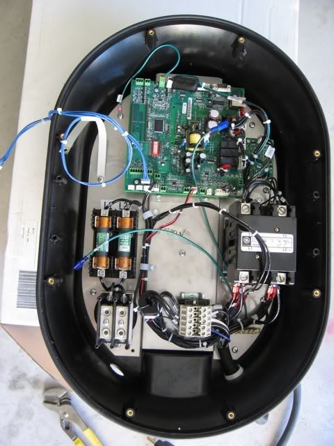
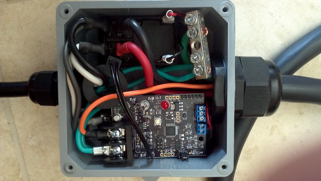
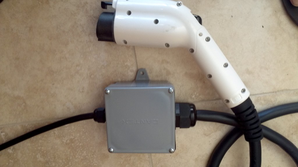
Inside EVSE's linked from around this board and the web.

Blink...

http://evseupgrade.com/pic/?blnk3" onclick="window.open(this.href);return false;
pic


http://evseupgrade.com/pic/?blnk2" onclick="window.open(this.href);return false;
pic


http://evseupgrade.com/pic/?blnk1" onclick="window.open(this.href);return false;
pic
 
AV...

http://electriceptor.files.wordpress.com/2010/12/2010_12_01-10_04_24-003-evse-install-1600.jpg" onclick="window.open(this.href);return false;
2010_12_01-10_04_24-003-evse-install-1600.jpg


http://electriceptor.files.wordpress.com/2010/12/2010_12_01-10_03_55-002-evse-install-1600.jpg" onclick="window.open(this.href);return false;
2010_12_01-10_03_55-002-evse-install-1600.jpg


http://i110.photobucket.com/albums/n94/olmstead_photos/EVSE/Bothhalves.jpg" onclick="window.open(this.href);return false;
Bothhalves.jpg


http://i110.photobucket.com/albums/n94/olmstead_photos/EVSE/BoardPic1.jpg" onclick="window.open(this.href);return false;
BoardPic1.jpg
 
Nissan/Panasonic...

http://a1.sphotos.ak.fbcdn.net/hphotos-ak-snc6/hs047.snc6/167765_10150099113684844_704969843_6081039_2231493_n.jpg" onclick="window.open(this.href);return false;
167765_10150099113684844_704969843_6081039_2231493_n.jpg
 
GE Wattstation...

http://i1180.photobucket.com/albums/x419/badamsfx/My%20Nissan%20Leaf%20forum/Wattstation_guts.jpg" onclick="window.open(this.href);return false;
Wattstation_guts.jpg
 
Yes, the Weekend project EVSE should be highly water resistant, the EVSE is in a UL listed watertight housing with NEMA 4X rated Cable Glands.

It's pretty small for a 30A EVSE.
 
What is the function of the loop / sensor around the black and white wire? Does that monitor amperage?
 
Are you planning to mount the PCB and grounding block to the case somehow?
It seems like if you really shook it hard you might be able short something out.
 
chris1howell said:
Nissan/Panasonic...

http://a1.sphotos.ak.fbcdn.net/hphotos-ak-snc6/hs047.snc6/167765_10150099113684844_704969843_6081039_2231493_n.jpg" onclick="window.open(this.href);return false;
167765_10150099113684844_704969843_6081039_2231493_n.jpg
I'm curious which components in there Phil upgraded for his Rev 1 and Rev 2 mods? Does anybody know?
 
I think ... that the Mod-L1 EVSE has these modifications:
1. the "big" transformer (white label at the right end) replaced with a "universal" DC power supply.
2. a component near the middle is replaced that is too marginal for 240v operation.
3. the input cable (right end) and plug replaced
4. a label affixed
5. new items "glued" in place
6. other?
 
Chris,
When packaged this way, is there a way to change/set the Max-Amps from the outside?

When might you be able to sell your almost-finished Kit (still needs the input plug attached)?
 
DarkStar said:
garygid said:
2. a component near the middle is replaced that is too marginal for 240v operation.
I understand that to be the two relays in the middle (the two verticle boxes under the three wires with the zip-tie between them).
I wonder if Phil only needs to de-pot enough around those 2 relays to replace them, or whether he has to de-pot and re-pot the whole board. I hear de-potting is labor intensive.

Also curious if anyone has an AFTER picture of the modified EVSE?

Also, is the Rev2 just a firmware change from the Rev1? Or are there further hardware changes required for Rev2?
 
Volusiano said:
Also curious if anyone has an AFTER picture of the modified EVSE?

Somebody did tell me that they took their EVSE Upgrade unit apart after they got it back from Phil. Said is was a real SOB to drill out the black stuff in the screw holes. Unfortunately, I don't think this person took photos and I don't actually really remember who it was to ask again.
 
I don't think the relays are replaced, they are rated at 240V 20A.

Gary... I can not change the current setting in the config shown, its set to 30A max. I am working on a bluetooth module so maybe soon...

I am not sure when a finished product will be avalible, Zerocarbonworld in the UK has a prototype now. And I am working hard to tie up all the loose ends....
 
Chris,
GREAT work.

I believe the relays are NOT changed, but some component roughly right below (in the picture above) the tan horizontal fuse.

SPX uses a "waterproof" rotary switch installed in the face of the case.
Might that work for you (to select Max-Amps)?
 
Yeah Gary it would not be too hard, a rotary switch with a resistor in series for each option routed into an analog input would work fine.

For a fixed EVSE, it is not necessary. I just set the max current it in software based on the breaker and wiring close it up and let it go...
 
chris1howell said:
Yeah Gary it would not be too hard, a rotary switch with a resistor in series for each option routed into an analog input would work fine.

For a fixed EVSE, it is not necessary. I just set the max current it in software based on the breaker and wiring close it up and let it go...

I think the idea is to match the EVSE to the circuit ampacity availble, so you won't blow the breakers. For now, almost nothing can use more than 16A @ 240V, but a Tesla. In the future, with 6.6KW chargers, the Tesla Model S, the Ford Fusion EV, etc, this will not be the case, so you want the ability to set the EVSE to match the circuit ampacity. Options needed are few: 12A (for 15A circuits), 15A (for 20A circuits), 24A (for 30A circuits), and 32A (for 40A circuits). you only need 4 settings to handle it all.
 
Back
Top