AC charging does not work, 2012 Leaf in Sweden

My Nissan Leaf Forum

Help Support My Nissan Leaf Forum:

This site may earn a commission from merchant affiliate links, including eBay, Amazon, and others.

MikeEcho

Member
Joined
Sep 7, 2021
Messages
21
I discovered that our Leaf does not charge on AC chargers (we have not tried DC Chademo since the one in our city is removed permanently).

1. After charging, one blue light comes on for few seconds and it then turns off.
2. I tried to measure resistance/diode polarity on ground/pilot but did not see low resistance. In one direction I read about 0.4 Mega Ohms and in reverse it seemed open.
3. I suspected that the 12 V battery was poor (showing 12.2 V), so I charged it overnight. I installed it and saw it again showing 12.2V on the car and 12.38 free. I suspected a poor battery, and bought and installed a new battery. It did not solve the problem. I also noted that a 2.2 A (that drops to 1.5A) is drawn when all I install the battery and all of the lights are off.
4. I got these from leaf Spy Pro:
C1109 0008 ABS Battery Voltage Abnormal BRC-75
C118A 0108 ABS E-Driven Int Brake System BRC-124
U11 OD 0108 ABS E-Driven Intelligent Brake Comm BRC-130
C118C 0108 ABS EV/HEVSystem BRC-126
Ok None---> AIIR BAG
U1000 0008 BCM CAN Comm Circuit
82562 0008 BCM Low Voltage BCS-69
82604 0008 BCM Shift PN Diag CAN SEC-81
826EF 0008 BCM
C1A62 0108 BRAKE Control Mod Pwr Supply BR-53
C1A6E 0108 BRAKE EV/HEV System BR-146
C1A70 0108 BRAKE Brake Control System BR-160
U1511 0108 BRAKE Pwr Supply Backup Unit Comm BR-184
829A0 2968 CHARGER N/CHG Port Engage Err VC-95
829C1 236C CHARGER EVSE VC-98
82820 0028 CHARGER Quick Charger VC-63
U1008 876C CHARGER Quick Charger Comm VC-49
82902 4228 CHARGER OBC Memory Error VC-91
Ok None---> PARKING BRAKE
Ok None ---> EPS
>P3173 00C1 EV /HEV On Board Charger Sys EVC-236
Ok None---> HVAC
Ok None---> HV BATTERY
82109 0008 IPDM E/R
Ok None---> METER
Ok None ---> MOTOR CONTROL
U1300 0108 MULTI AV AV Comm Ci rcuit AV-93
U1240 0208 MULTI AV Switch Conn AV-93
U1232 0108 MULTI AV St Angle Sen Calib AV-88
Ok None---> SHIFT
U1A05 0008 TCU USB Comm AV-199

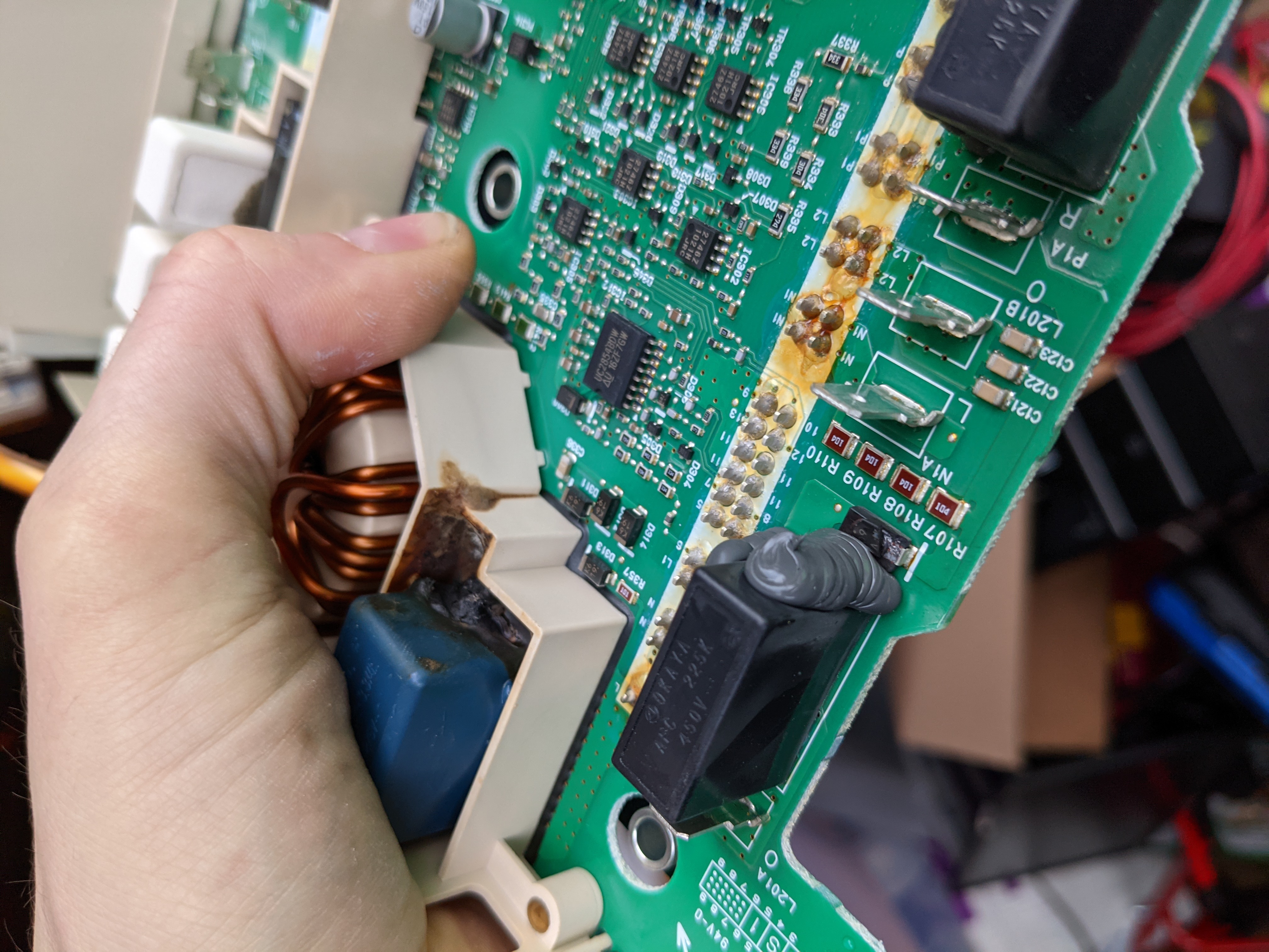
I guess some of the above codes were due to low 12V battery, but now I am pretty sure that the On-board charger is in trouble. I am wondering what will be the best next action, taking it to the dealership (I think I can reach it with the remaining charge), or buying a second hand on-board charger from an accident write-off Leaf [does it need to be exactly the same]. I wonder if more experienced forum members can help me decide.
As you can guess, I have searched and read about Leafs with similar problems in this forum.
 
Almost all of those codes are related to a weak 12V.

Charge that "new" 12V with either a "smart" charger that will drive it up to 14.4V and hold it there to desulfate the plates, or a power supply that you can control. Once you have a good strong 12V battery then most of those should go away or can be cleared, then you can find and focus on the real problem.

An OBC fault could occur with a weak 12V also, similar to the symptoms you have.

The 1.5A draw when everything is off is not normal, that would drain it in one day. but that may be something held partially ON due to the weak battery. Try to get that reading again with a known fully charged battery, OCV, and then connected V and I. Then pull the DTCs to see if anything changed.

You can swap out the OBC with a salvage unit if it is found to be bad.
 
It did not work. Still got the following errors:

B29C1 236C CHARGER EVSE VC-98
P3173 OOCO EV /HEV On Board Charger Sys EVC-236
 
MikeEcho said:
It did not work. Still got the following errors:

B29C1 236C CHARGER EVSE VC-98
P3173 OOCO EV /HEV On Board Charger Sys EVC-236
Well it is good that all the other errors got cleared out with a strong 12V.

The B29C1 gets thrown for any of 5 conditions related to the EVSE, when the PWM is interrupted or has an error, and if the AC mains is missing, if present before the start command, or if present after the stop command. Possible Causes to be checked are the harness, connectors, the charge port, the OBC, the EVSE. There are some troubleshooting steps in the FSM to help pinpoint it.

The P3173 is an VCU code that says the OBC reported a problem over the CAN buss.

Maybe you have access to a different EVSE that you could try to see if it works, to check for a bad EVSE, or have someone try your EVSE on their car to see if it works?

Also inspect down into the pins of the EVSE for debris or corrosion, check wiring for broken or pinched wires, demate and mate connectors, inspect for corrosion or oxidation of pins and sockets, etc. Basically rule out everything else down but the OBC since it is difficult to reach the OBC. When you get to the OBC then the cover can be removed to inspect the circuit board. Or just replace it with a known good salvage unit.
 
Hi I have same problem with mine as well with my 2015 Leaf
Start charging at home with J1772 and everything initiates as normal but charging shuts off after 2 minutes
 
NewtoEV said:
Hi I have same problem with mine as well with my 2015 Leaf
Start charging at home with J1772 and everything initiates as normal but charging shuts off after 2 minutes

You shouldn't assume that you have the exact same issue though...

Are you using the stock Nissan EVSE? Have you tried L2 charging at a public EVSE? Any DTC codes from LeafSpy that you can post here?
 
nlspace said:
MikeEcho said:
It did not work. Still got the following errors:

B29C1 236C CHARGER EVSE VC-98
P3173 OOCO EV /HEV On Board Charger Sys EVC-236
Well it is good that all the other errors got cleared out with a strong 12V.

The B29C1 gets thrown for any of 5 conditions related to the EVSE, when the PWM is interrupted or has an error, and if the AC mains is missing, if present before the start command, or if present after the stop command. Possible Causes to be checked are the harness, connectors, the charge port, the OBC, the EVSE. There are some troubleshooting steps in the FSM to help pinpoint it.

The P3173 is an VCU code that says the OBC reported a problem over the CAN buss.

Maybe you have access to a different EVSE that you could try to see if it works, to check for a bad EVSE, or have someone try your EVSE on their car to see if it works?

Also inspect down into the pins of the EVSE for debris or corrosion, check wiring for broken or pinched wires, demate and mate connectors, inspect for corrosion or oxidation of pins and sockets, etc. Basically rule out everything else down but the OBC since it is difficult to reach the OBC. When you get to the OBC then the cover can be removed to inspect the circuit board. Or just replace it with a known good salvage unit.

After removing the cables and (completely disconnecting the 12V) and removing the battery safety lock, I opened the cover of OBC while it was on the car (a very difficult M8 bolt is located at the bottom middle, the rest was easy, also needed security torx driver bit....). Any way, I removed the top board (after struggling with top left screw and bottom left...the remaining came off easily with Philips screw driver) and did not suspect much as it did not see any signs.
I removed the cable connectors from the bottom board but could not separate it from the housing, I think it is strongly connected by thermal paste and did not want to risk breaking the board.

Anyway, I went back to the top board and measured the D547, and it is open. On close inspection, there is a V shaped mark on top surface of it. I think this is a good indication that this diode needs changing. I have some good experience in soldering with regular Through hole circuits, but not much success with SMD.
I have some questions:

1.Is it a bad idea to try to replace the D547 with a regular TH diode (that I have, with 1000V rating at home)? Or is it best to buy a SMD replacement diode of the same size [any suggestions? I will look for it in Digikey or Farnell etc.]?
2. Unfortunately, during the removal of the top left screw I managed to damage the brittle [ferrite] cover and wiring of an inductor nearby (L504, label on the inductor I221).
3. Is there a good company in EU to send the board for repairs there rather than attempting this myself? or is it best to buy better SMD soldering equipment for myself?

1.
 
nlspace said:
MikeEcho said:
It did not work. Still got the following errors:

B29C1 236C CHARGER EVSE VC-98
P3173 OOCO EV /HEV On Board Charger Sys EVC-236
Well it is good that all the other errors got cleared out with a strong 12V.

The B29C1 gets thrown for any of 5 conditions related to the EVSE, when the PWM is interrupted or has an error, and if the AC mains is missing, if present before the start command, or if present after the stop command. Possible Causes to be checked are the harness, connectors, the charge port, the OBC, the EVSE. There are some troubleshooting steps in the FSM to help pinpoint it.

The P3173 is an VCU code that says the OBC reported a problem over the CAN buss.

Maybe you have access to a different EVSE that you could try to see if it works, to check for a bad EVSE, or have someone try your EVSE on their car to see if it works?

Also inspect down into the pins of the EVSE for debris or corrosion, check wiring for broken or pinched wires, demate and mate connectors, inspect for corrosion or oxidation of pins and sockets, etc. Basically rule out everything else down but the OBC since it is difficult to reach the OBC. When you get to the OBC then the cover can be removed to inspect the circuit board. Or just replace it with a known good salvage unit.

After removing the cables and (completely disconnecting the 12V) and removing the battery safety lock, I opened the cover of OBC while it was on the car (a very difficult M8 bolt is located at the bottom middle, the rest was easy, also needed security torx driver bit....). Any way, I removed the top board (after struggling with top left screw and bottom left...the remaining came off easily with Philips screw driver) and did not suspect much as it did not see any signs.
I removed the cable connectors from the bottom board but could not separate it from the housing, I think it is strongly connected by thermal paste and did not want to risk breaking the board.

Anyway, I went back to the top board and measured the D547, and it is open. On close inspection, there is a V shaped mark on top surface of it. I think this is a good indication that this diode needs changing. I have some good experience in soldering with regular Through hole circuits, but not much success with SMD.
I have some questions:

1.Is it a bad idea to try to replace the D547 with a regular TH diode (that I have, with 1000V rating at home)? Or is it best to buy a SMD replacement diode of the same size [any suggestions? I will look for it in Digikey or Farnell etc.]
2. Unfortunately, during the removal of the top left screw I managed to damage the brittle [ferrite?] cover and wiring of an inductor nearby (L504, label on the inductor I221).
3. Is there a good company in EU to send the board for repairs there rather than attempting this myself? or is it best to buy better SMD soldering equipment for myself?
4. An easy solution could be shorting the D547 on the board (with a short copper wire soldered between its leads) and adding the diode that I have to the charging port's pilot cable. Any comments about this?

[edit: searched for "electronics repair specialist" and found one in our city. I will pay a visit on Monday as it does not work during weekends.]

[edit 2: the damaged inductor should be this one: https://ds.yuden.co.jp/TYCOMPAS/ut/detail?pn=NS12575T221MNV%20&u=M]
 
Good catch to find a bad diode.

On my board D547 has a second diode in parallel on the same pads, D552 marked "271" which makes me think it is a Zener. The marking on D547 and over 12 other similar diodes is a tiny "c1"; based upon the size and marking i think it is a Toshiba 1SS352, but anything with a similar rating would work.

The L504 inductor is part of the low voltage power supply created using IC511 a NJM2374 PWM DC/DC converter and needs to be functional or replaced if damaged.

Most any small signal TH diode could be used for testing over the weekend until you can get a proper repair, as long as L504 is not open or shorted.

Does your board look like this, solder one lead to the post of pin 13 of CN502 and the other end to far end of D547 using the same diode polarity.
E74yt2P.png
 
nlspace said:
Good catch to find a bad diode.

On my board D547 has a second diode in parallel on the same pads, D552 marked "271" which makes me think it is a Zener. The marking on D547 and over 12 other similar diodes is a tiny "c1"; based upon the size and marking i think it is a Toshiba 1SS352, but anything with a similar rating would work.

The L504 inductor is part of the low voltage power supply created using IC511 a NJM2374 PWM DC/DC converter and needs to be functional or replaced if damaged.

Most any small signal TH diode could be used for testing over the weekend until you can get a proper repair, as long as L504 is not open or shorted.

Does your board look like this, solder one lead to the post of pin 13 of CN502 and the other end to far end of D547 using the same diode polarity.
E74yt2P.png

Thanks for all the help and suggestions,
My board (from 296A0 3NA6A) also has a second parallel diode (D552).
UmC1A5A.jpg

zoomed around the suspect:
wXpQYYT.jpg
 
i measure 0.596V drop across the diode pair using the diode check function of the DMM, and open in the reverse direction.

Did you remove one of the diodes to measure--how could you determine the diode was open when there are two in parallel?

What is the previous history of this car and this failure to charge situation--has someone tried to solve this previously and marked the diode?
 
nlspace said:
i measure 0.596V drop across the diode pair using the diode check function of the DMM, and open in the reverse direction.

Did you remove one of the diodes to measure--how could you determine the diode was open when there are two in parallel?

What is the previous history of this car and this failure to charge situation--has someone tried to solve this previously and marked the diode?

Hi.. My soldering iron is in a storage that I will visit on Tuesday. I measured the diodes in the circuit.
car history:
We purchased the car in 2016 with 25 000 km on ODO. [the car was sold just coming out of warranty] and it now has 47000 on ODO. The battery SOH is 78% at the moment. Never needed a repair and I was just about to change the brake pads.
When I opened the OBC, every screw seemed in mint condition, so I did not feel that someone had an earlier attempt.
 
MikeEcho said:
.... I measured the diodes in the circuit.

So both diodes are blown then?

From the history, it does seem that OBC had not likely been opened; it looks like someone scratched a ">" in the direction of current flow..? Hard to tell if it is cracked.
 
nlspace said:
MikeEcho said:
.... I measured the diodes in the circuit.

So both diodes are blown then?

From the history, it does seem that OBC had not likely been opened; it looks like someone scratched a ">" in the direction of current flow..? Hard to tell if it is cracked.

I doubt if the V mark is not related to the internal damage, but there is a little change that it is left on the diode by my crude multimeter probes. The diode is so small that I hardly could see what I was doing there while measuring.

I also add that in diode/connectivity test on my multimeter, on one side I read open and on the other side, I read 481 (unit?).
with the 20 Mega Ohm resistance measurement, one side was open and the reverse direction shows 4 (Mega Ohms).

I also see some signs of dust/explosion in figure below (on the white connector of the blue cable and on the white stripe of the lower board:
MuF0w5y.jpg
 
There is thread on here with a good picture of a blown diode on the power board, but i couldn't find it right now.

The debris on the faston connector of the blue wire may be from this diode located below the black capacitor with the gray sealant globbed along its side and edge, and above the ("L" for blue) faston tab and resistor string of R107-R110 as shown in your picture.

The discoloration on the white stripe is just solder flux residue that wasn't cleaned off before they sprayed a clear conformal coating, not a worry about that. There are 72 solder joints pairs in two columns across the power board; these joints connect to the high power semiconductors potted in a heatsink that i refer to as the waffle plate™ and damage to that is very rare.

[edit found the picture, good thread: https://mynissanleaf.com/viewtopic.php?f=30&t=28009#p549728]
PXL_20210217_001615835.jpg
 
MikeEcho said:
I also see some signs of dust/explosion in figure below (on the white connector of the blue cable and on the white stripe of the lower board:
That darkening reminds me of what I used to find on old television sets, especially tube ones, around parts or connectors that experience high DC and/or pulsed voltage. The high DC voltage seems to electrostatically attract dust, which accumulates over time. Usually it doesn't cause problems, unless it gets really bad. So this might be a red herring (not a true indication of a fault, even though it seems like it). But then again, in a sealed box with everything else very clean, this might not apply.

Just something to keep in mind.

[ Edit: resistors -> parts ]
 
MikeEcho said:
on one side I read open and on the other side, I read 481 (unit?).
with the 20 Mega Ohm resistance measurement, one side was open and the reverse direction shows 4 (Mega Ohms).
That sounds like the diode itself is working, or at least one of them is (and that's presumably all you need).

So is the earlier report of the diode reading open circuit incorrect?

Or does this mean that there is a fault in the wiring, as the diode is fine on the board, yet appears to be open circuit when measured from the AC port? Since you're in Sweden, I assume that your AC port is actually type 2, not Jl772 / type 1? So you measured from control pilot to protective earth and found it open circuit both directions? [ Edit: Duh. No, a 2012 would still be J1772, as confirmed by the cable used below. ]

If the problem is in the wiring, then there is no need to poke about in the on Board Charrger.
 
+1, coulomb is right that the diode(s) are likely good based upon the RESISTANCE measurement.

What brand is your meter--does it have a diode check function? That would be a better method to check.

How to check a diode

'
iu
 
coulomb said:
MikeEcho said:
on one side I read open and on the other side, I read 481 (unit?).
with the 20 Mega Ohm resistance measurement, one side was open and the reverse direction shows 4 (Mega Ohms).
That sounds like the diode itself is working, or at least one of them is (and that's presumably all you need).

So is the earlier report of the diode reading open circuit incorrect?

Or does this mean that there is a fault in the wiring, as the diode is fine on the board, yet appears to be open circuit when measured from the AC port? Since you're in Sweden, I assume that your AC port is actually type 2, not Jl772 / type 1? So you measured from control pilot to protective earth and found it open circuit both directions?

If the problem is in the wiring, then there is no need to poke about in the on Board Charrger.

I think I have confused everyone by my earlier sloppy reporting, the pilot-ground resistance also showed the similar (OL / Mega Ohm) range (similar to test on the leads of D547 diode on the board) and I equated Mega Ohm with open loop, which seems to be wrong. I read about the correct diode measurement method on Fluke's website and it could be possible for the diode to be healthy. Probably the best is to remove the diode from the circuit for testing.

The cable that I use is similar to this:
https://i.ebayimg.com/images/g/mjAAAOSwI25fNXEh/s-l1600.jpg
 
Back
Top