(Updated name from "TurboScan" to WattsLeft™ Monitor 7/24)
(Updated to include pricing table 2/23/13)
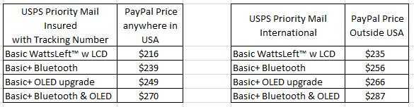
Here is the current price list.
If you are interested in getting a WattsLeft™ please email to [email protected]. I can send you a copy of the Quick Guide to show you what information can be displayed on the 15 selectable screens. Jump to bottom of Page 8 for lastest information.
I recently acquired some surplus Parallax SX28AC chips in DIP packages. After looking at the datasheet it seemed likely I could design an entire SOC meter around this single chip processor. As a result I took the leap and purchased an SX Key (USB) board which allows programming and in-circuit source-level debugging as well as some 50 MHz three pin resonators all from Parallax.
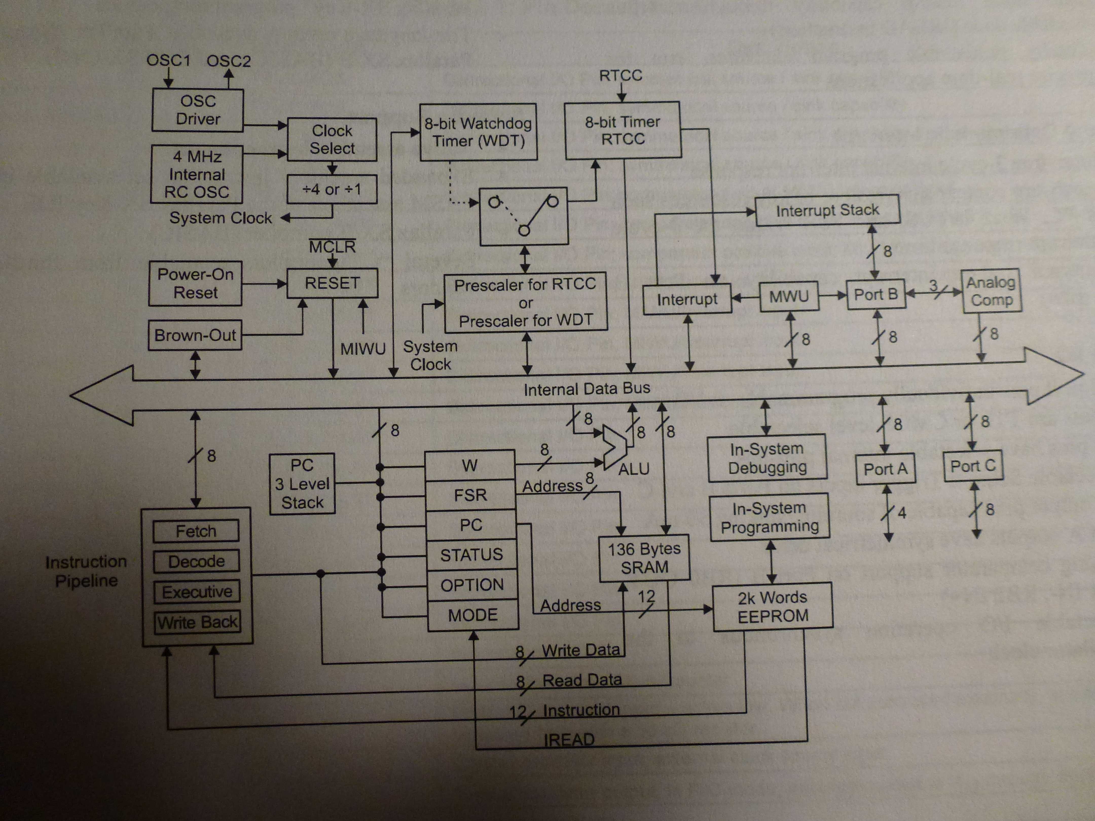
The SX28AC is a very basic single chip system with 2K words (12 bits) of EEPROM program storage, 136 bytes of RAM all inside a 28 pin package with 20 general purpose I/O pins. The instruction set is similar to the PIC16C5x series but with a few more instructions. It can run at up to 75 MHz with one instruction executed each cycle (except for jumps/calls, of course).
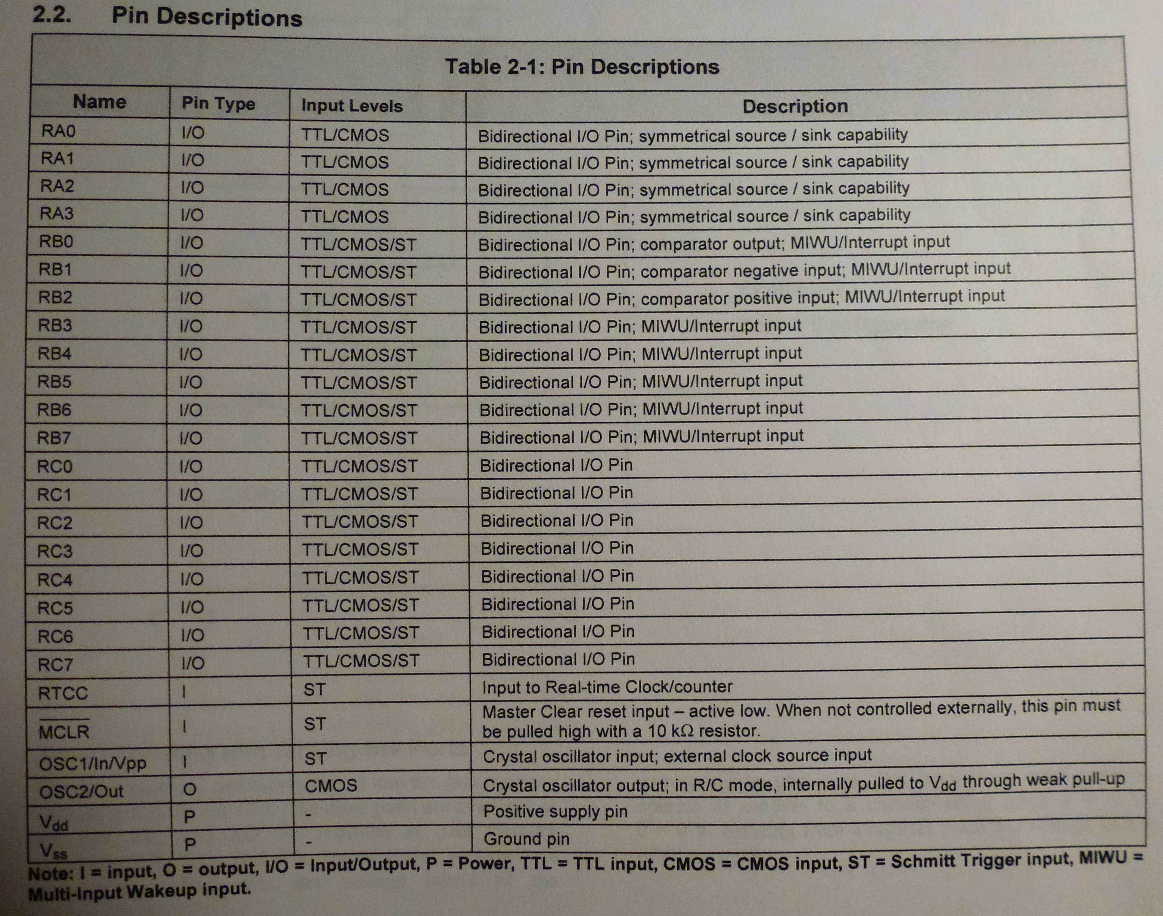
Here is the pin list.
Here is a summary of the instruction set.
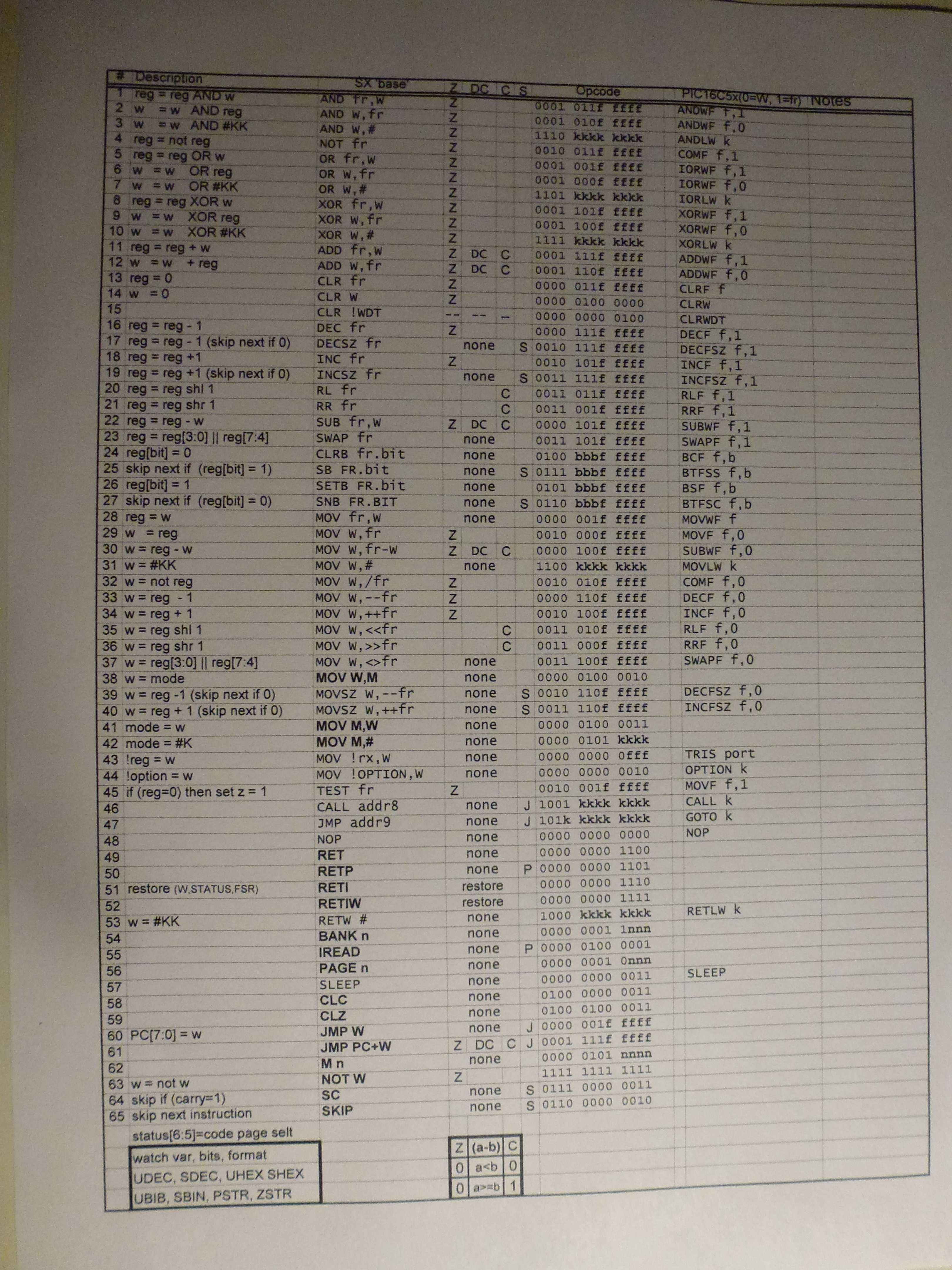
The clock rate for this project was selected to be 50 MHz so there would be 100 instructions executed per CAN bus bit (2 usec per bit). This seemed like it would give enough time to handle all the processing plus support a 57,600 baud serial out link to dump CAN frames to a PC.
There are no peripheral functions built-in like a CAN processor or Serial ports. It has only an 8-bit Real Time counter and a single Analog Comparator that can be selected to take over two of the 20 available I/O pins.
The original plan was to use only the SX28AC and a display. To do this I planned on using the Analog Comparator with one side connected to the CANH line and the other to a resistor divider set at a 3 volt level. I was not sure how well this would work since the idle level is 2.5 volts and dominant level is 3.5 volts. So for initial development I decided to remove this variable and just go with a standard MCP2551 CAN Transceiver. Once all the code is debugged and working I may go back and remove the MCP2551 and add the resistor divider.
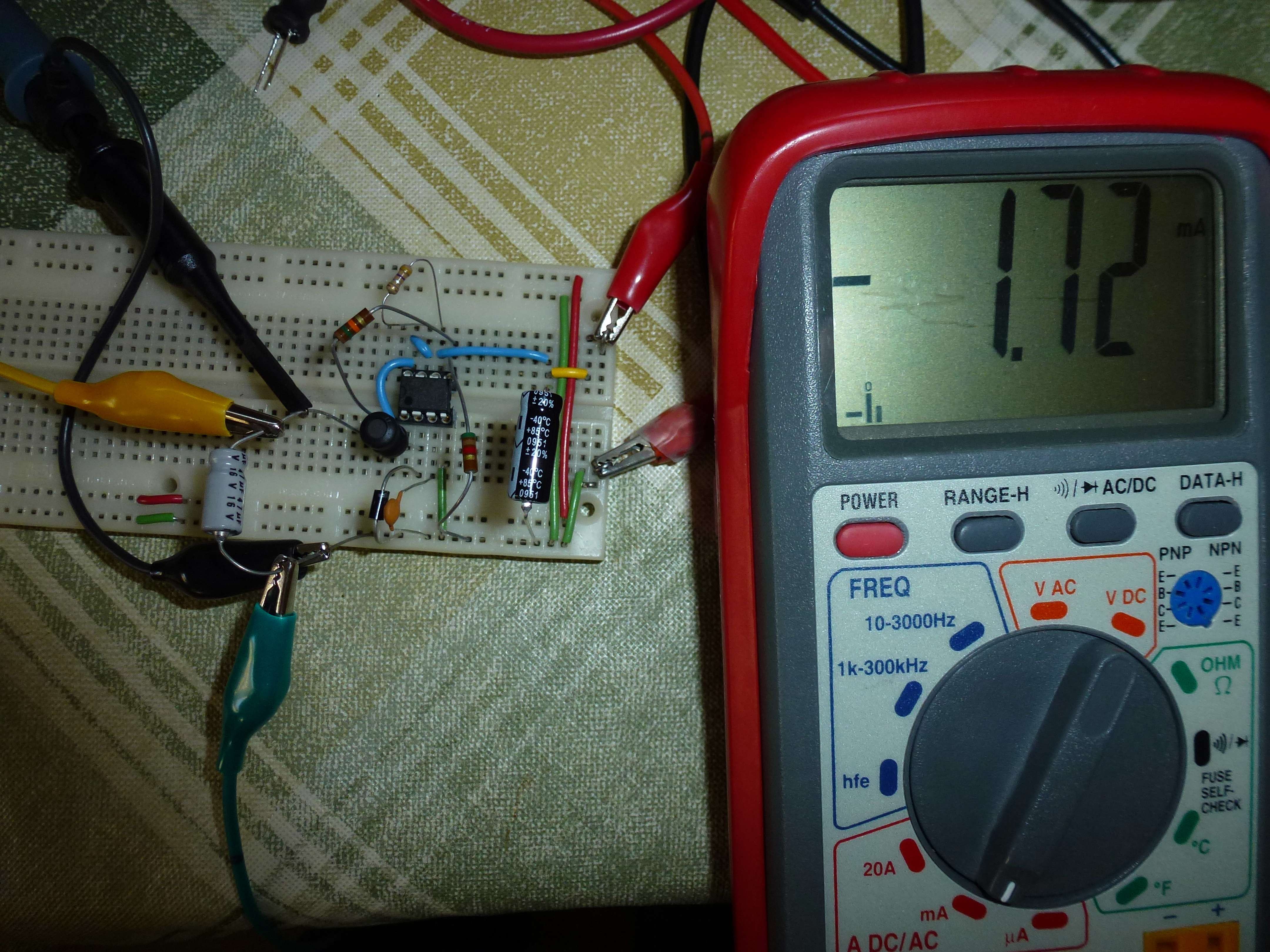
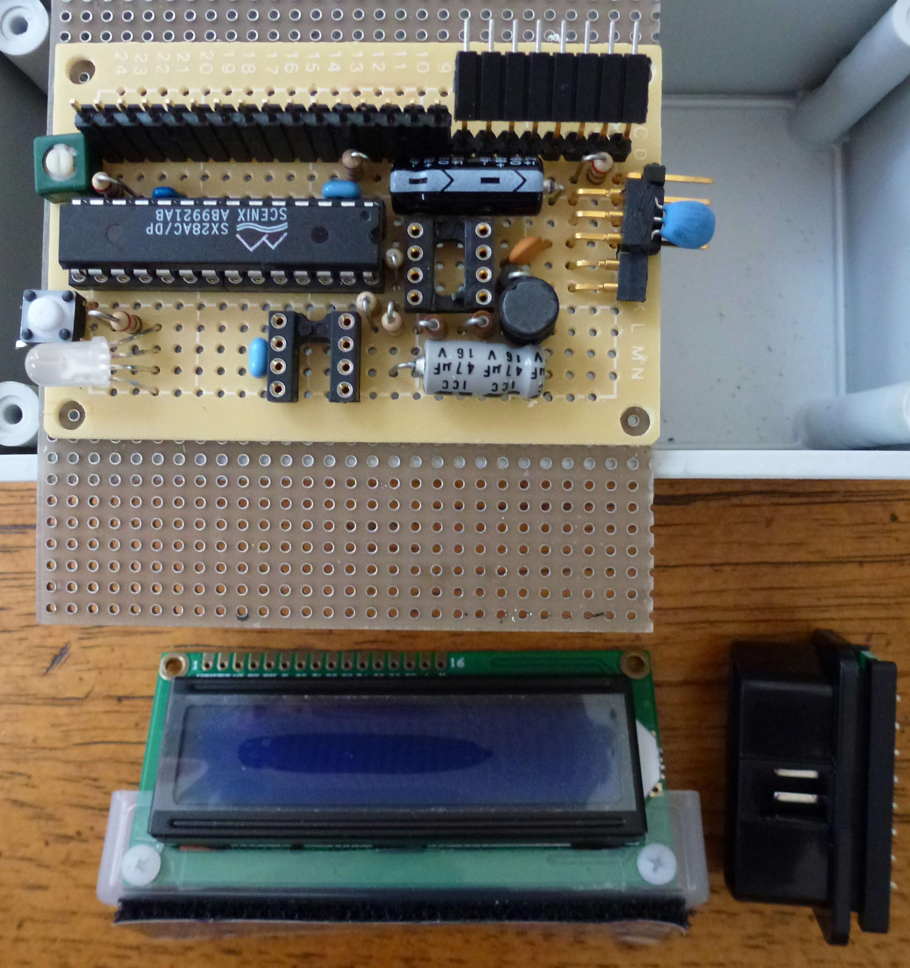
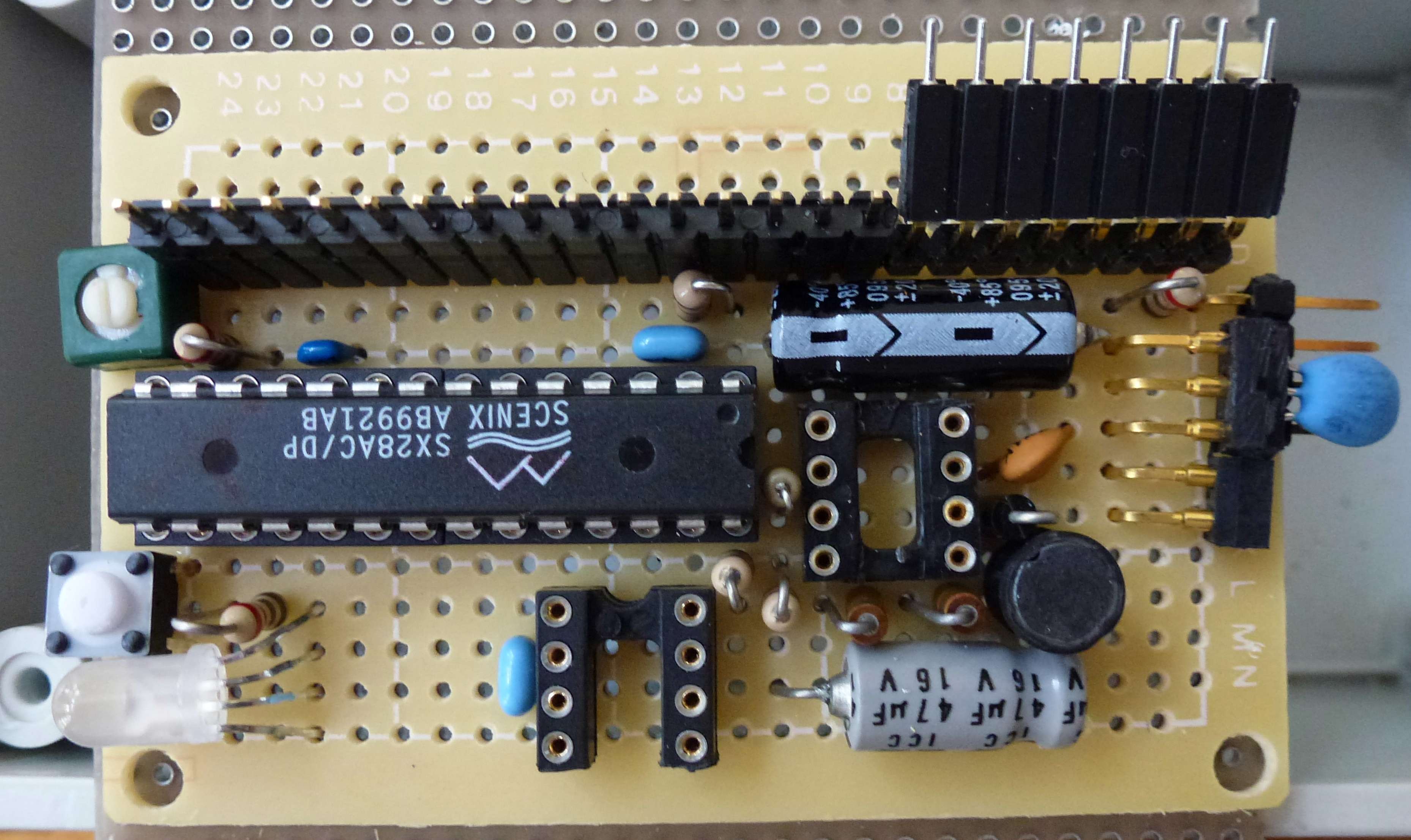
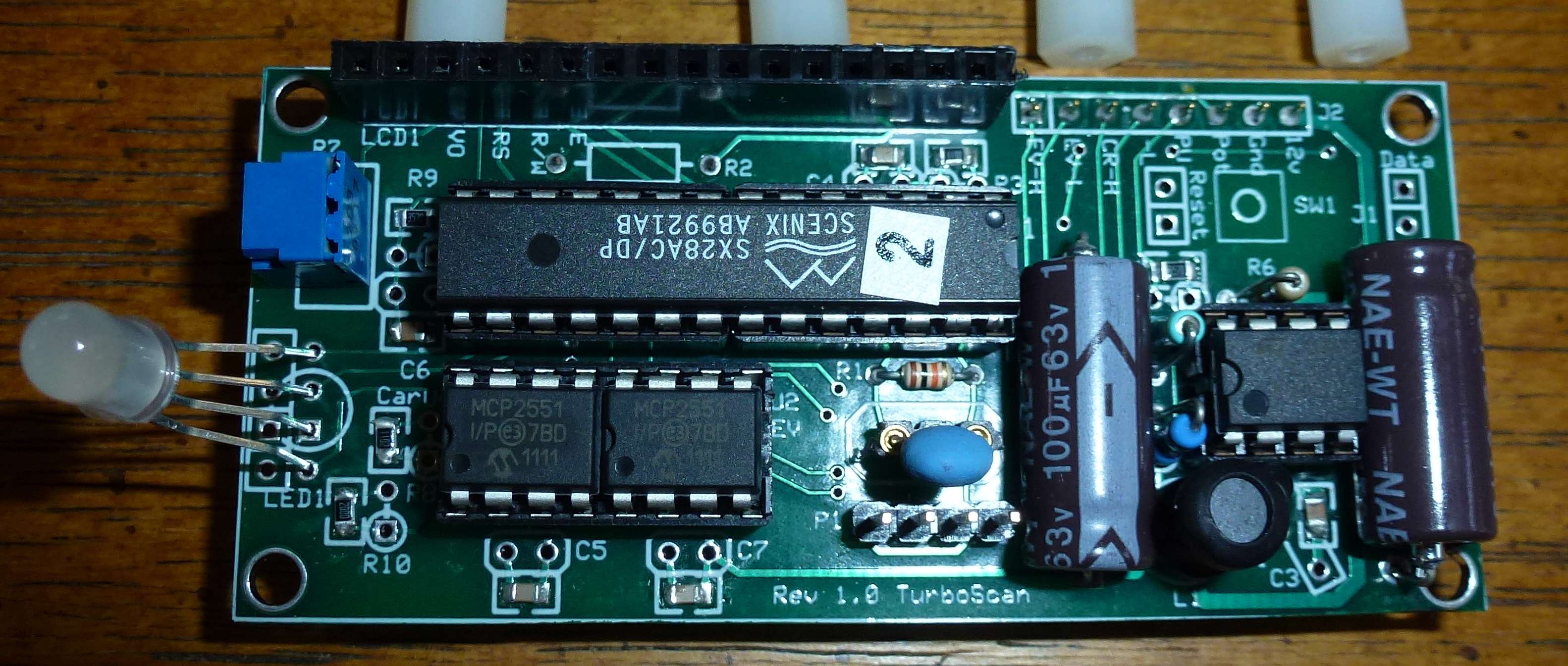
Below is what the first test board looked like. The 5 volt power is from an old car cell phone charger I had laying around. The black and orange wires are the Serial out lines which go to a 9 pin D connector. Most serial ports accept TTL level so you don’t need a converter to give +/- 12 volt levels. I am using a Serial to USB adapter with my laptop. The connector on the right with three pins is from the CAN cable. The blue dot is the 50 MHz resonator and the single button is for reset. Decoupling caps are under the ICs. The four pins on the left go to the SX-Key for programming/debugging.

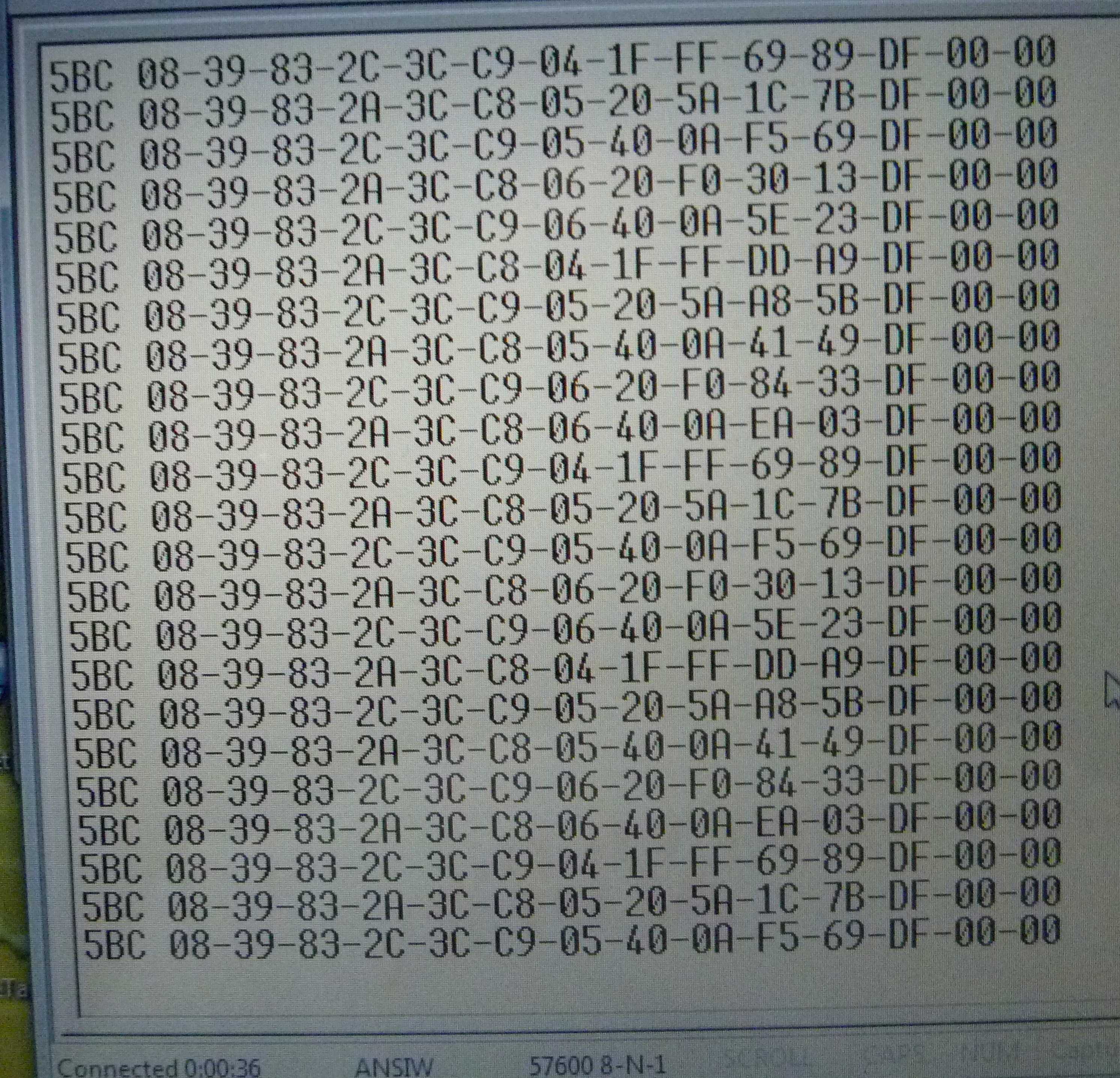
Here is a dump from the serial port of the raw SOC CAN messages including CRC. The code handles all the CAN bit processing (de-stuff, Serial to Byte, and CRC checking). Only messages with good CRC are passed on for processing. The code has two CAN Frame buffers so one can be processed by the main code loop for display/serial dump while the other is being filled in by the interrupt driven receive routine. Flags prevent overrunning the buffers. CAN frames that come in while both buffer are full are skipped.
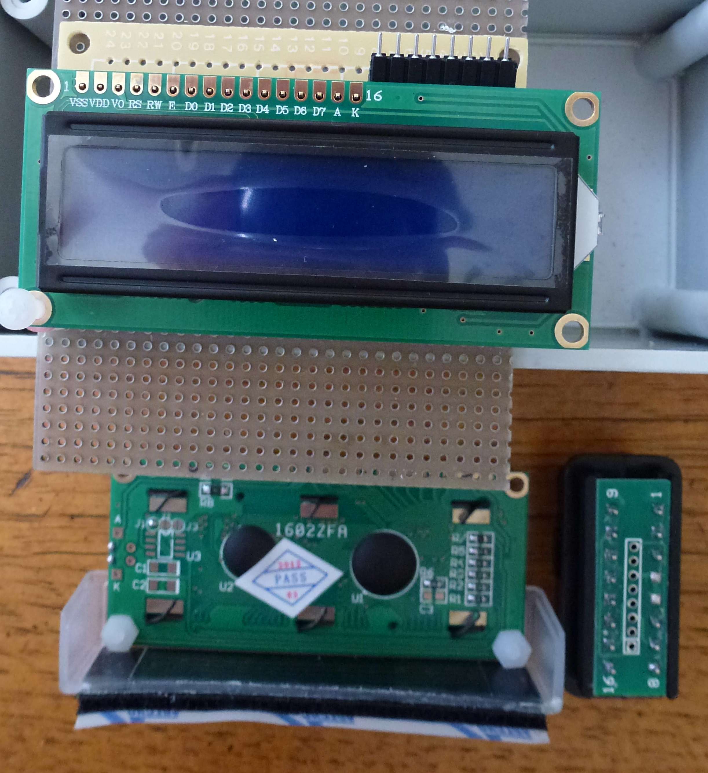
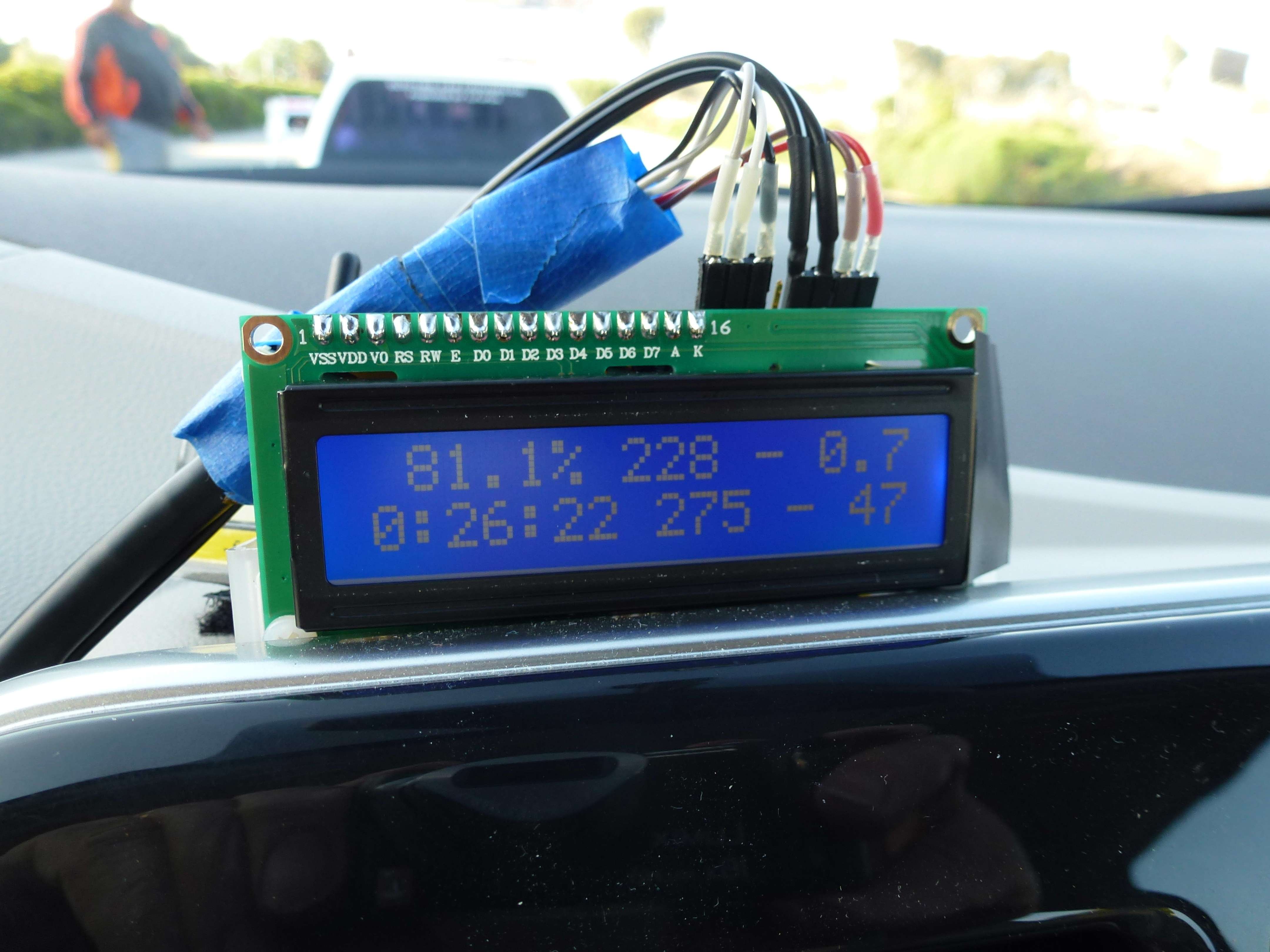
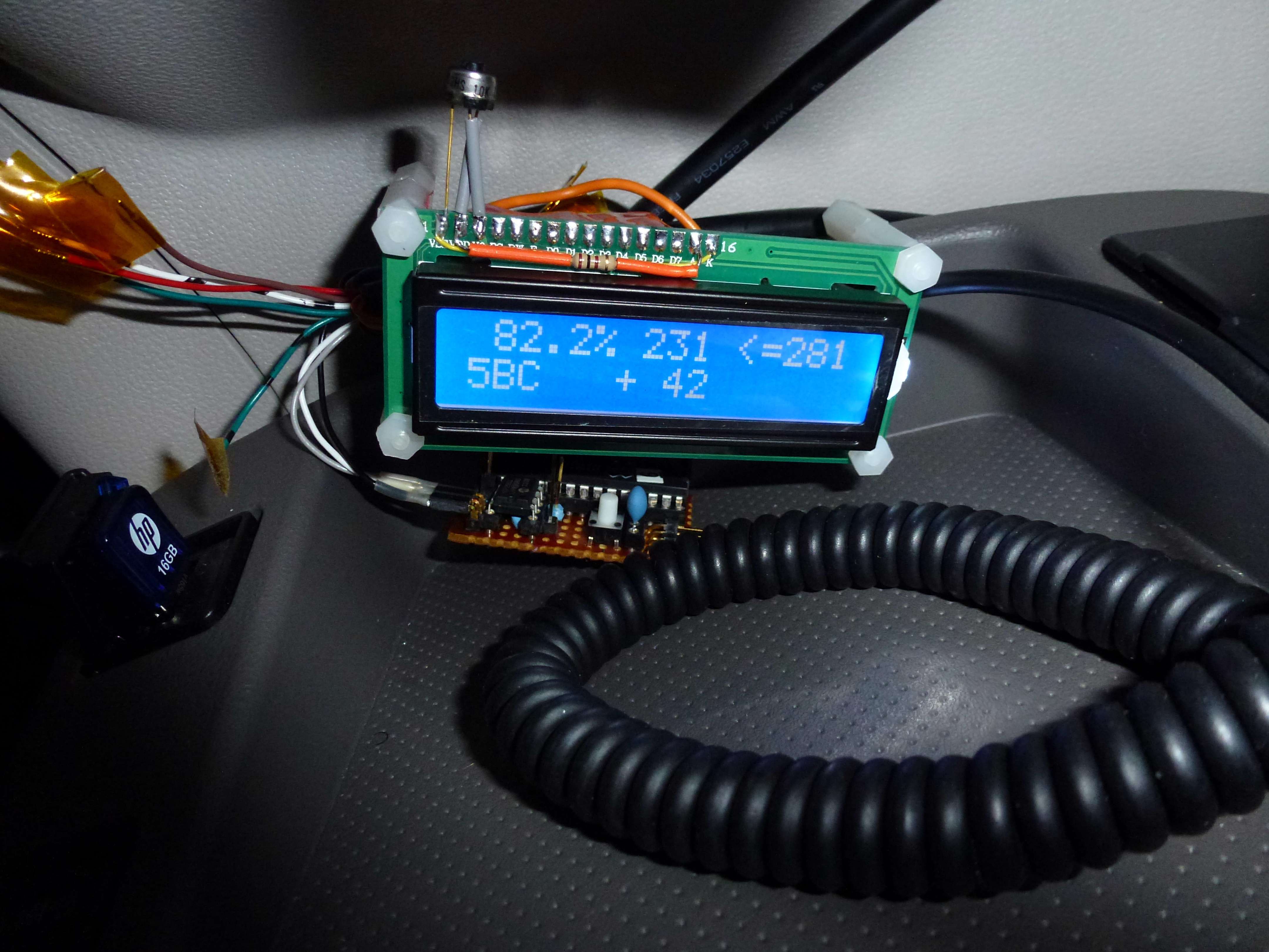
A 2 line by 16 character LCD display was selected to display the data to the user. The displays only cost $3.99 each including shipping.
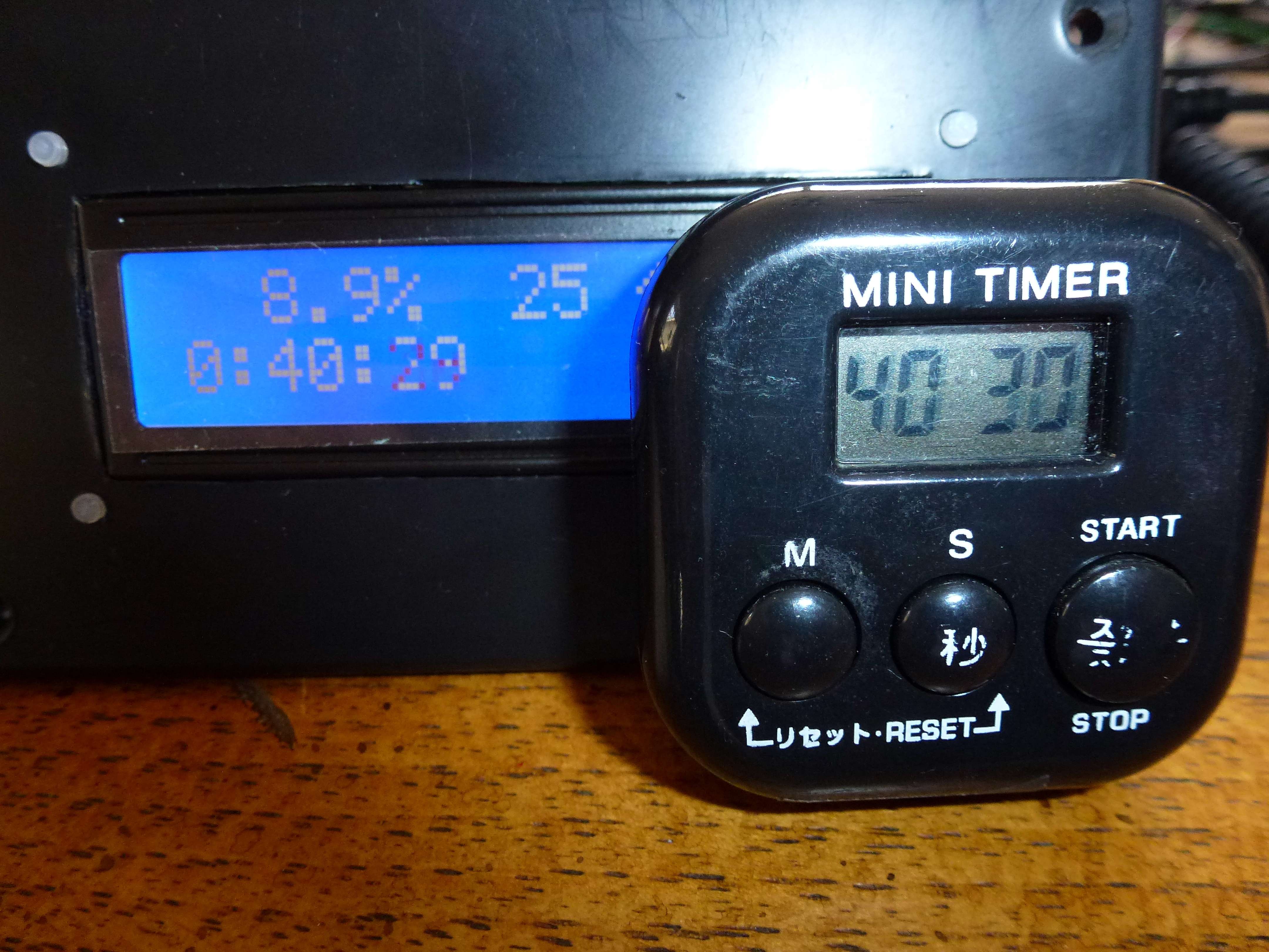
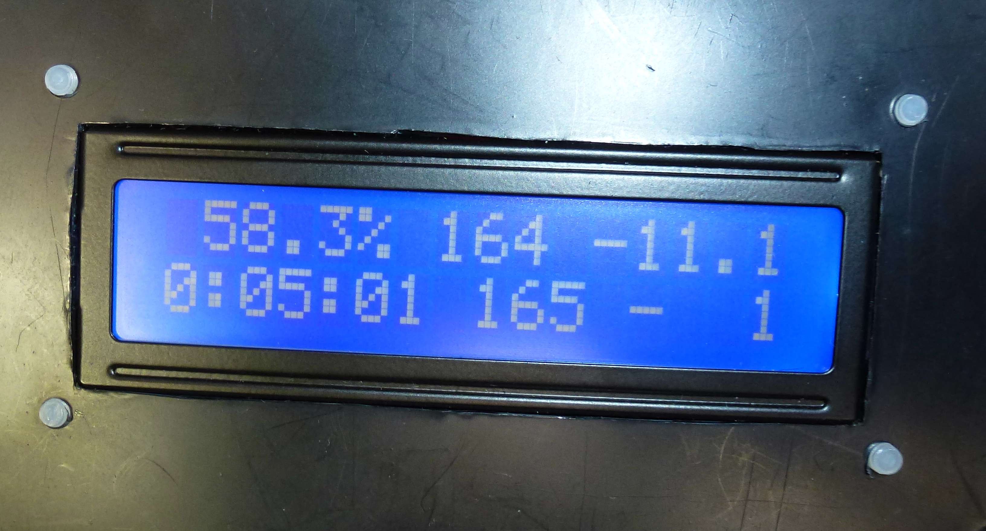
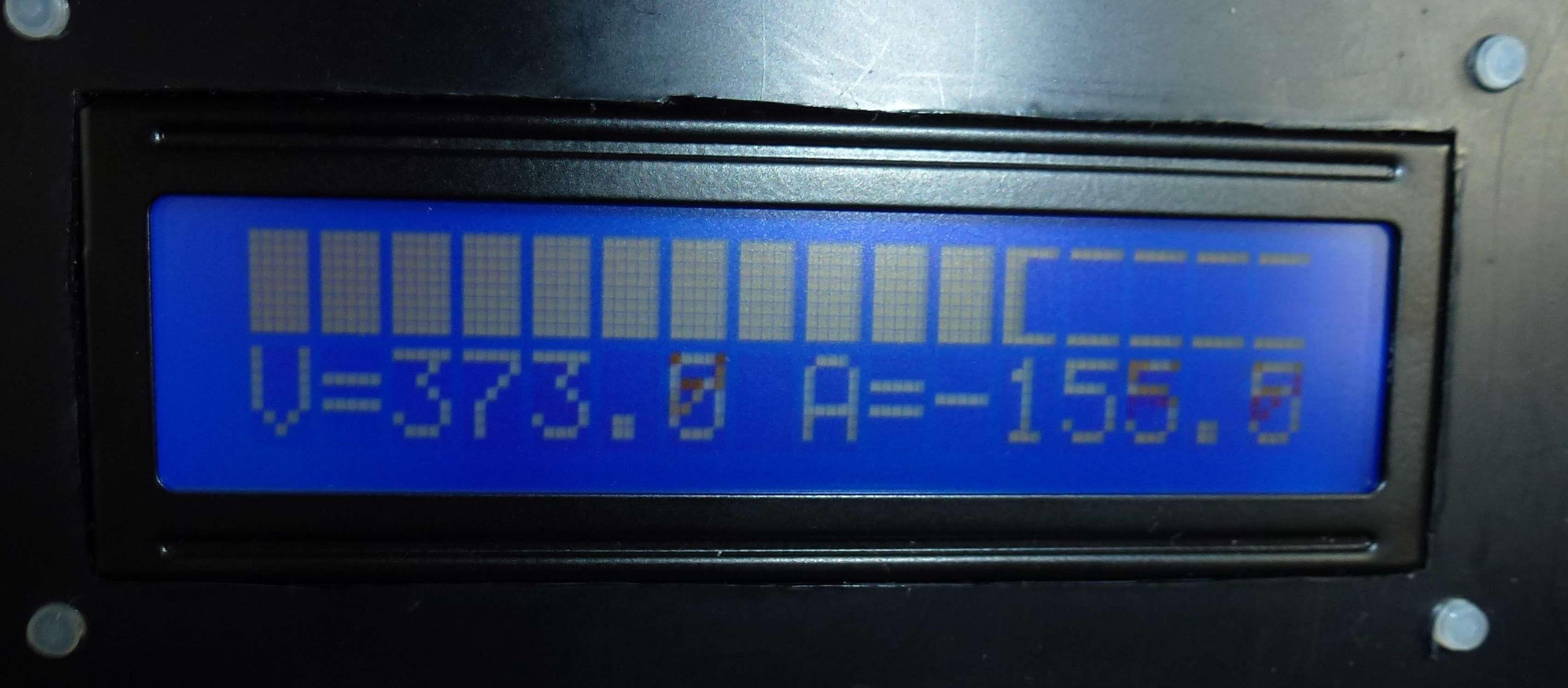
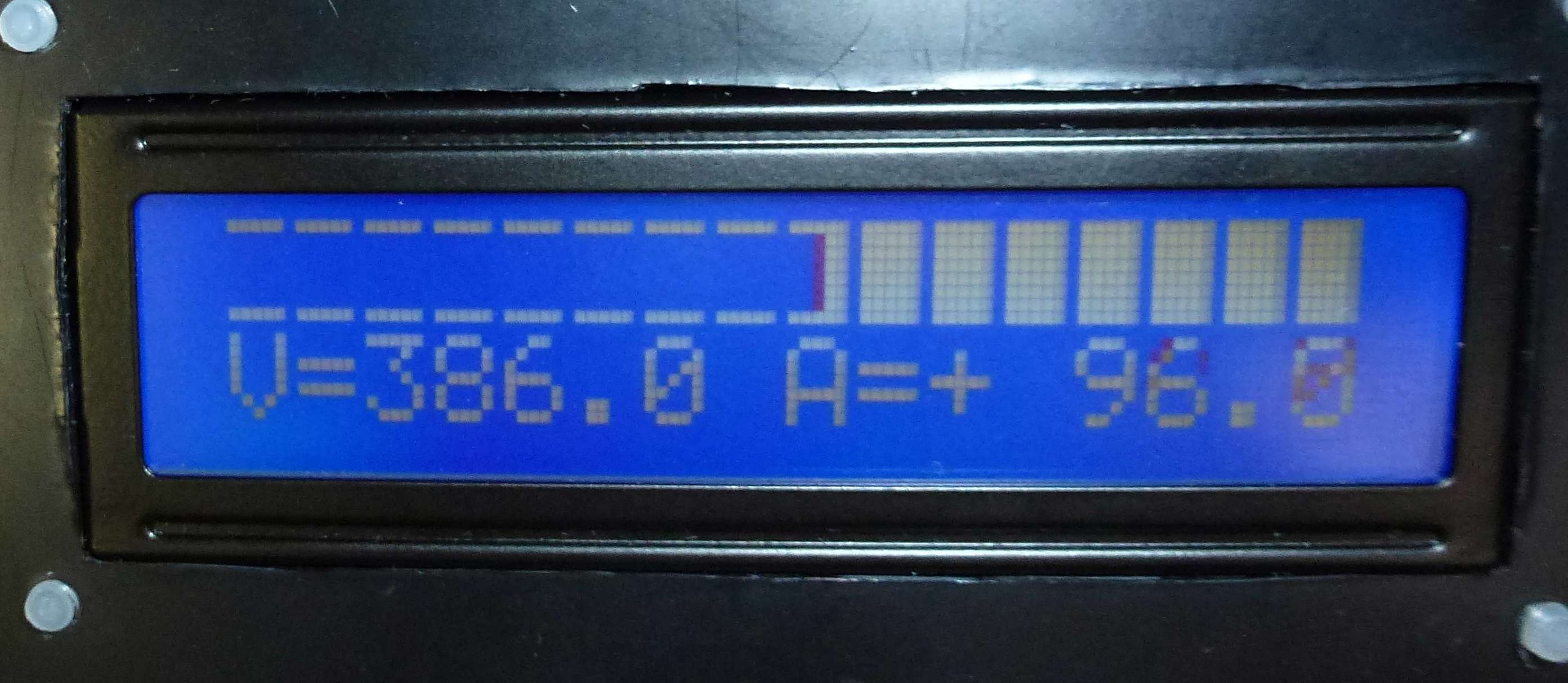
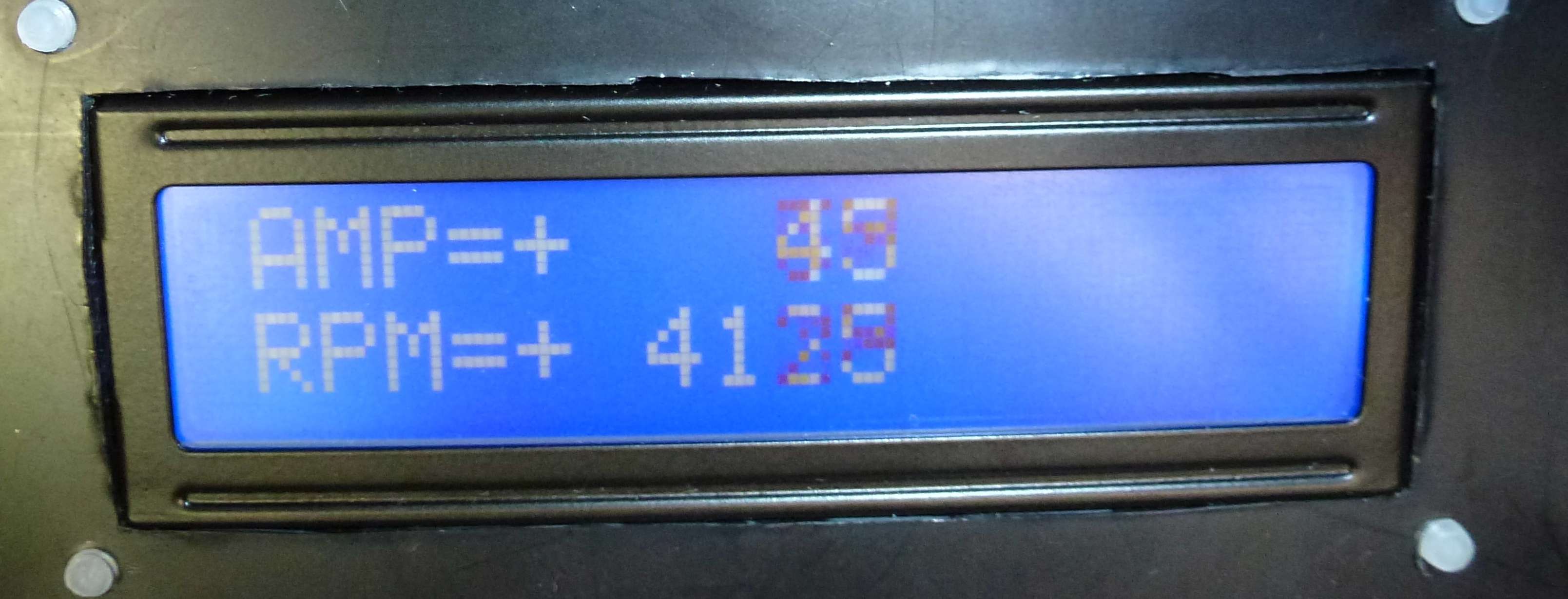
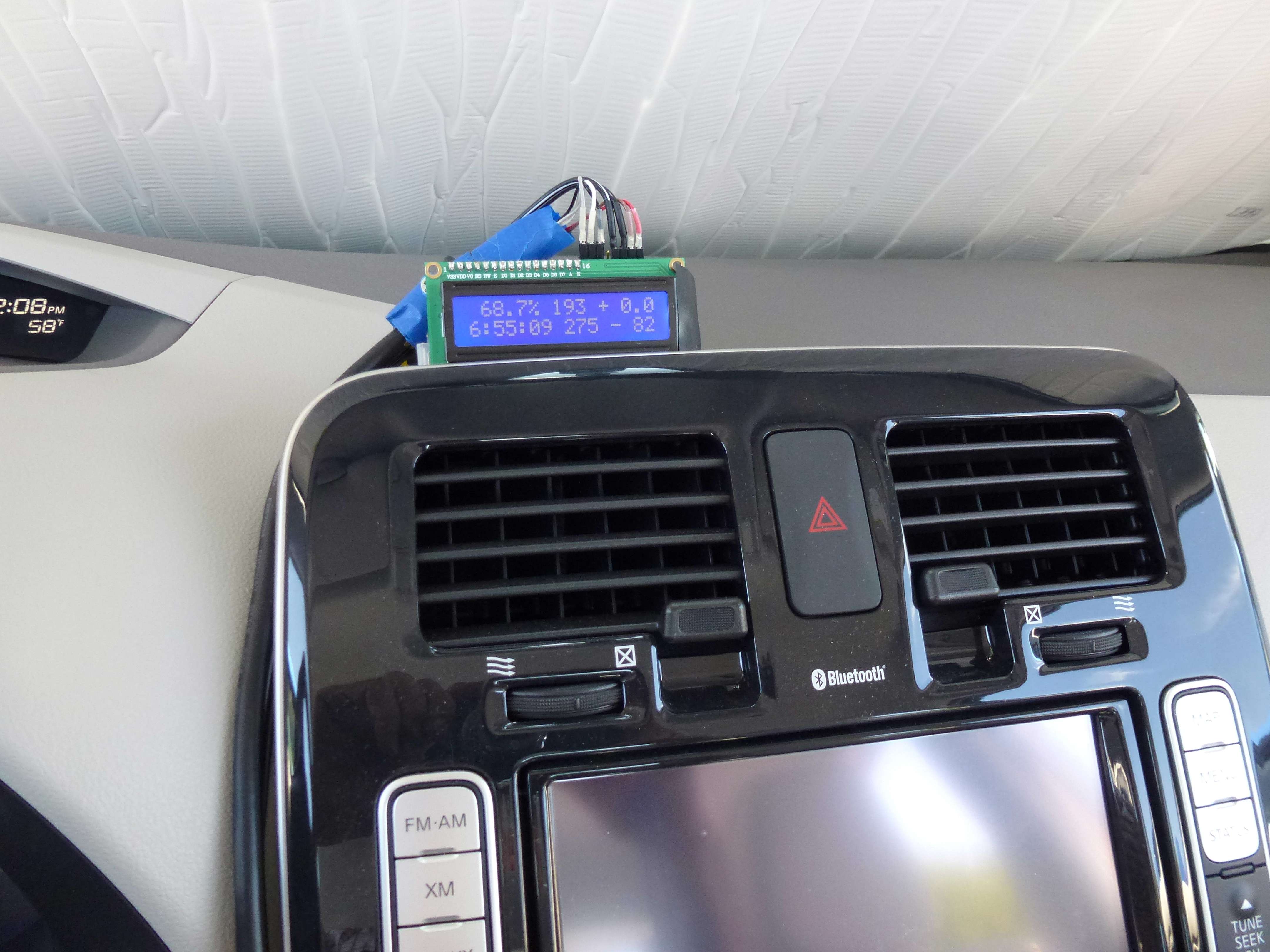
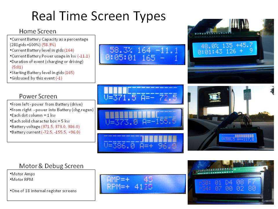
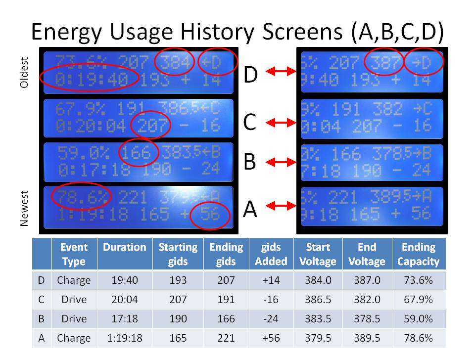
Here is the test board connected to the LCD display. There is a 10k pot sticking up to adjust contrast. With two lines of 16 characters there is room to show lots of information. This code version is showing SOC Percent, Gids number (my daughter wanted the 281 added to indicate the max value. The second line starts with the CAN Frame ID for SOC 0x5BC. Next I added trip/charge gauge. In this case it is showing the number of Gids that it took today to charge our Leaf back up to 80% (actually 82.2%, Blink said 3181 watts were used). While driving the number will be negative and show Gids used since the meter was powered on (car turned on).
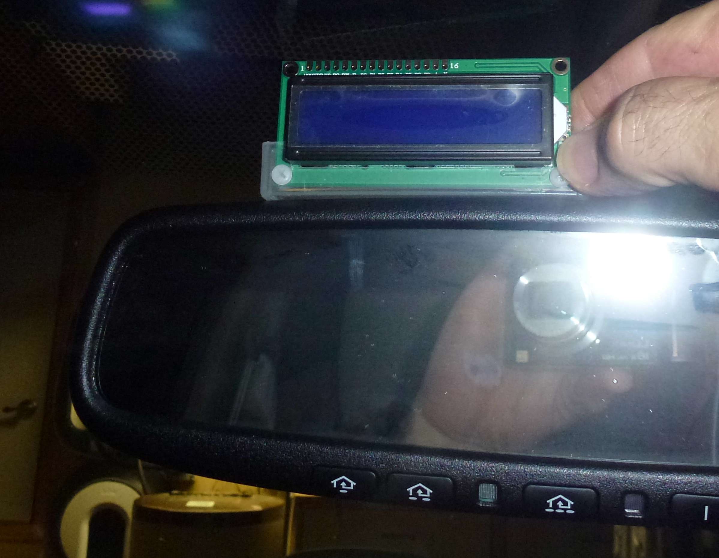
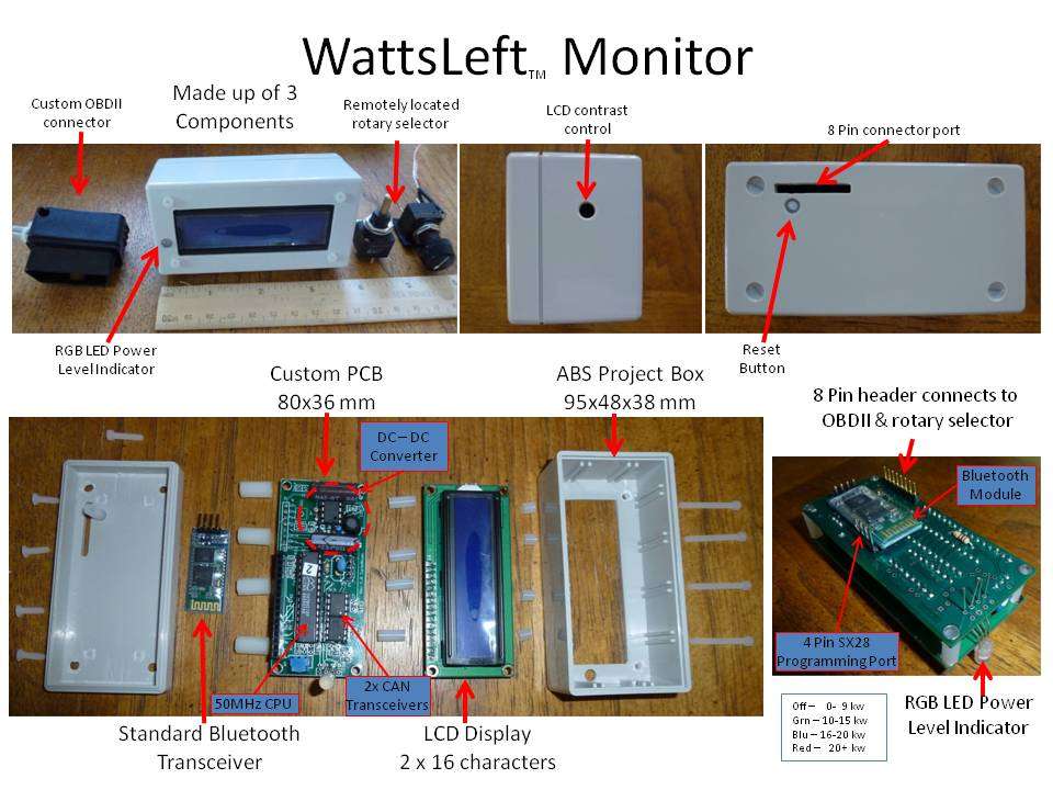
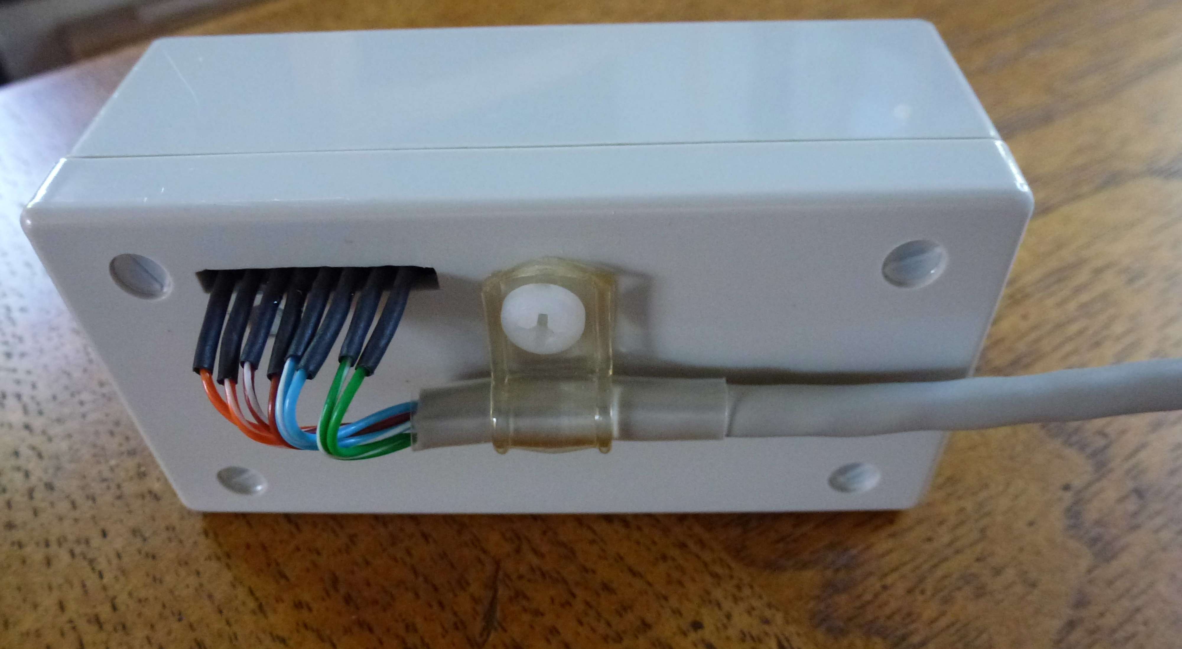
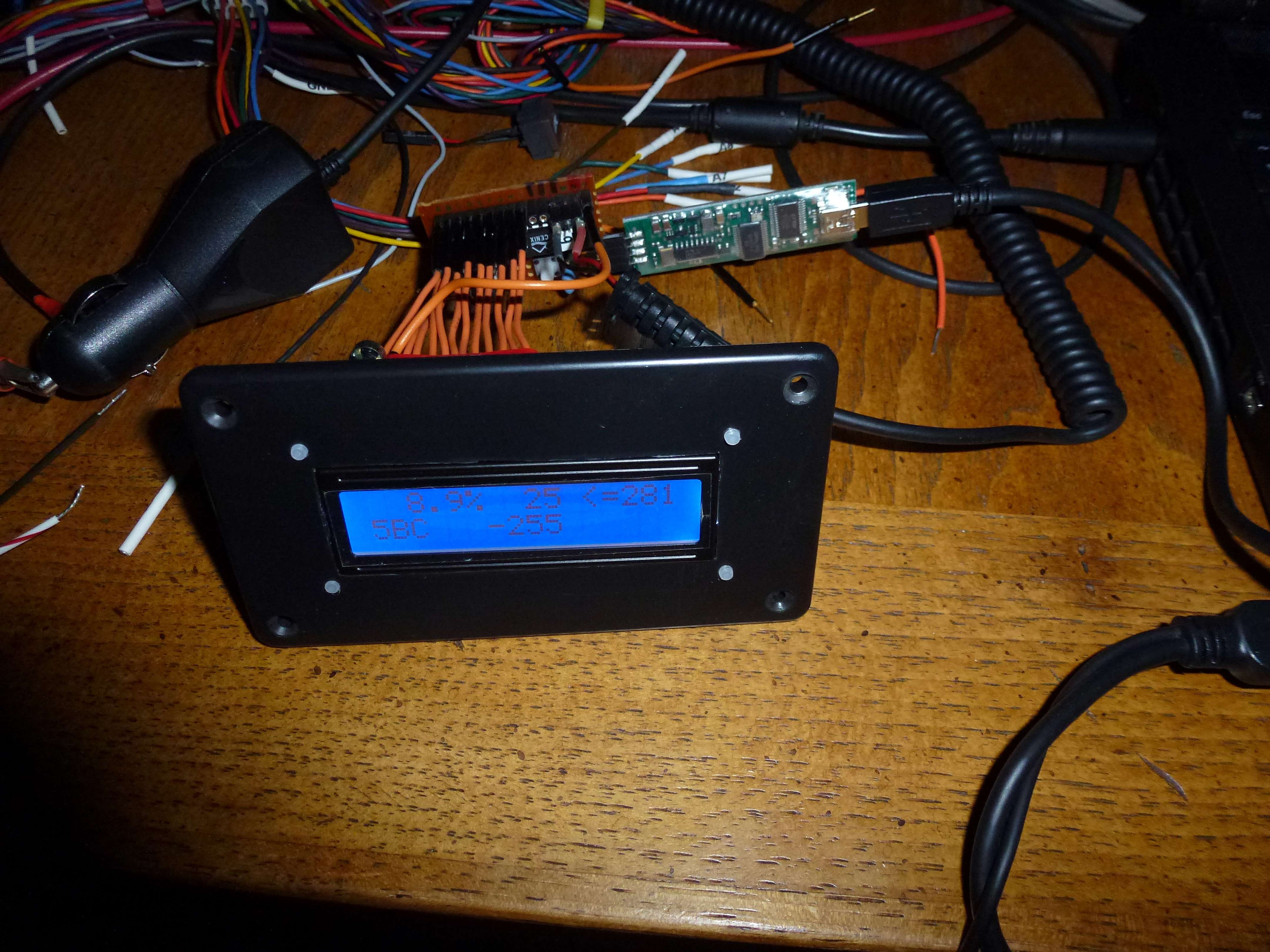
The hardware I have built so far is just for testing to allow debugging of the code. Here is the box that will hold the final version of the hardware which will plug directly into the display pins (no orange jumper wires). The cover has already been cut and display mounted. The 5 volt switching supply is shown laying in the bottom of the box. The box is 4 3/8 by 2 7/16 by 1 1/8.

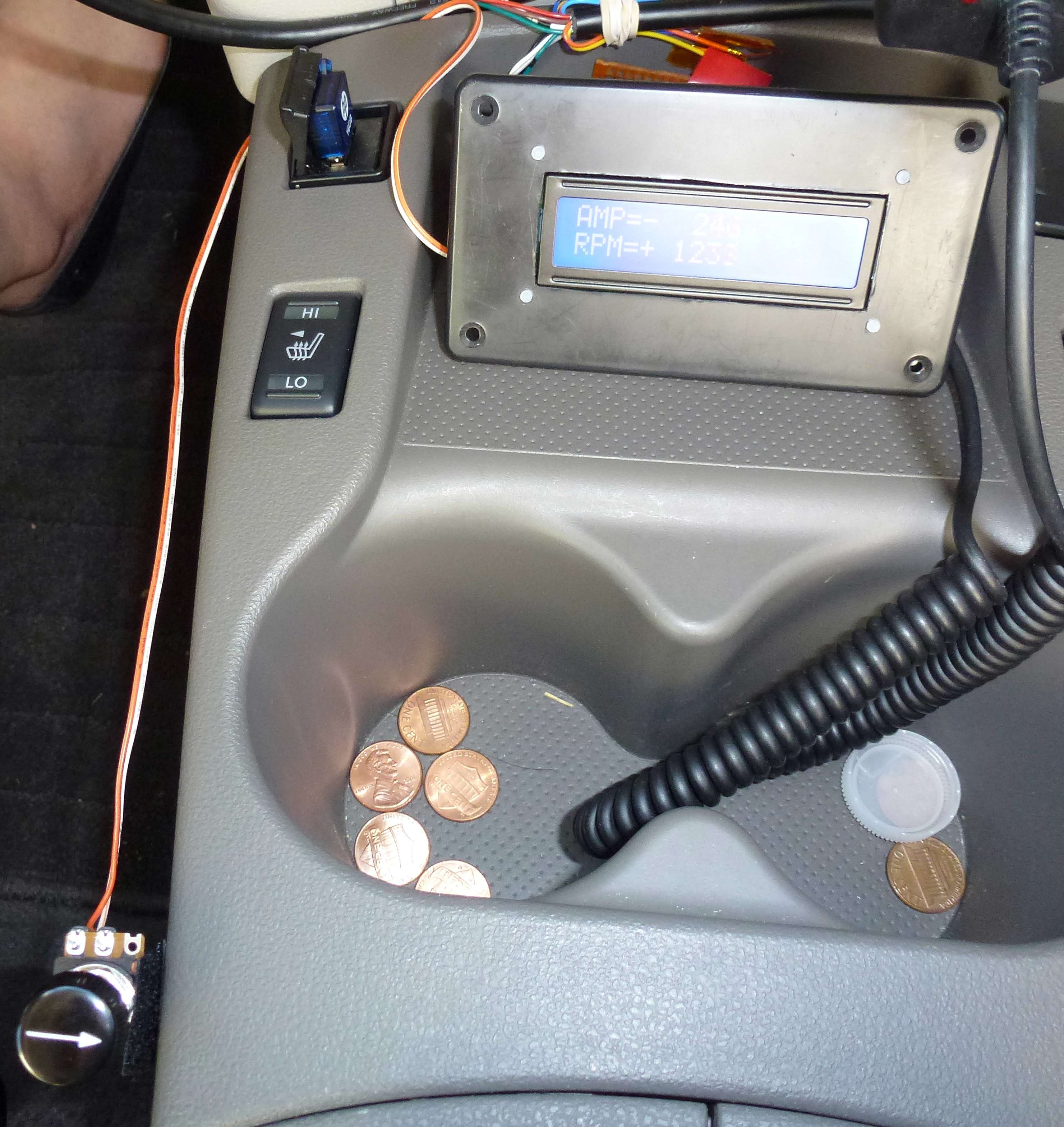
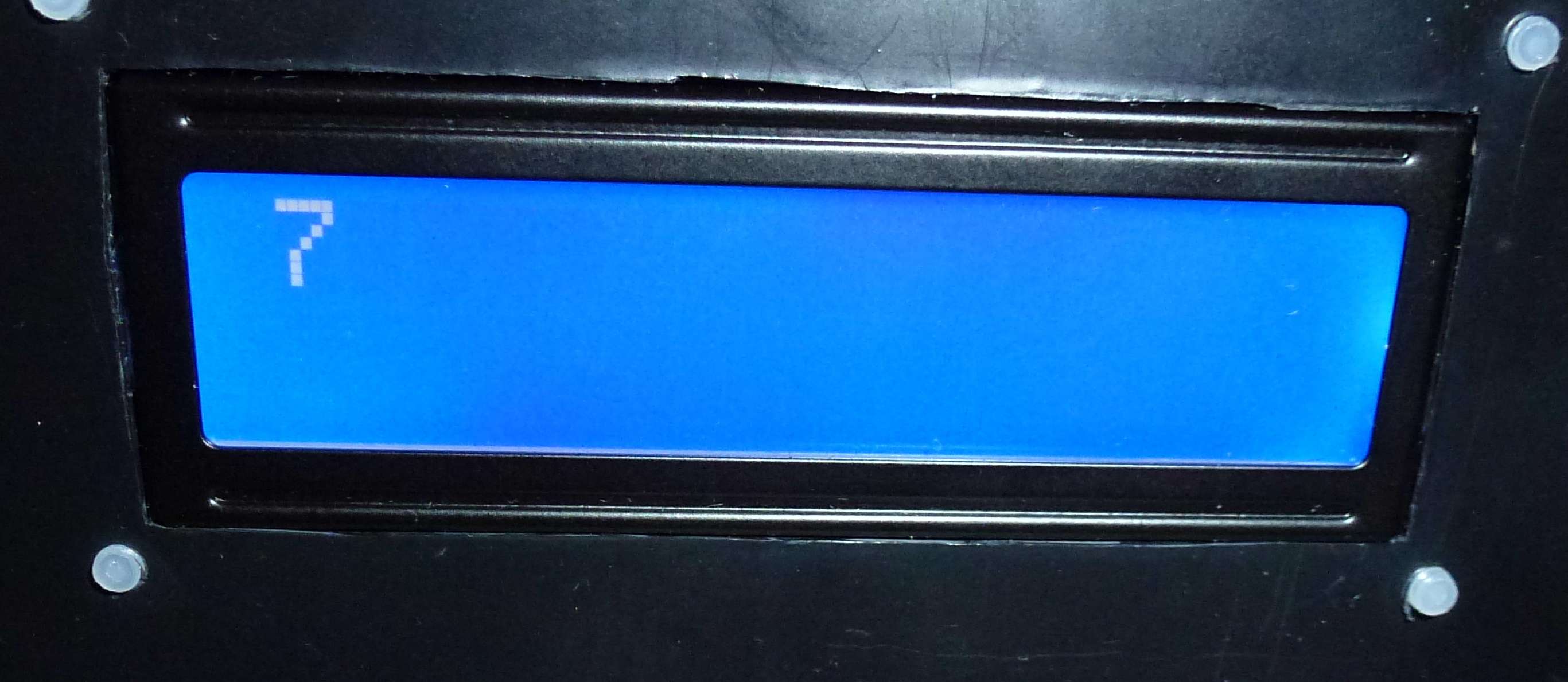
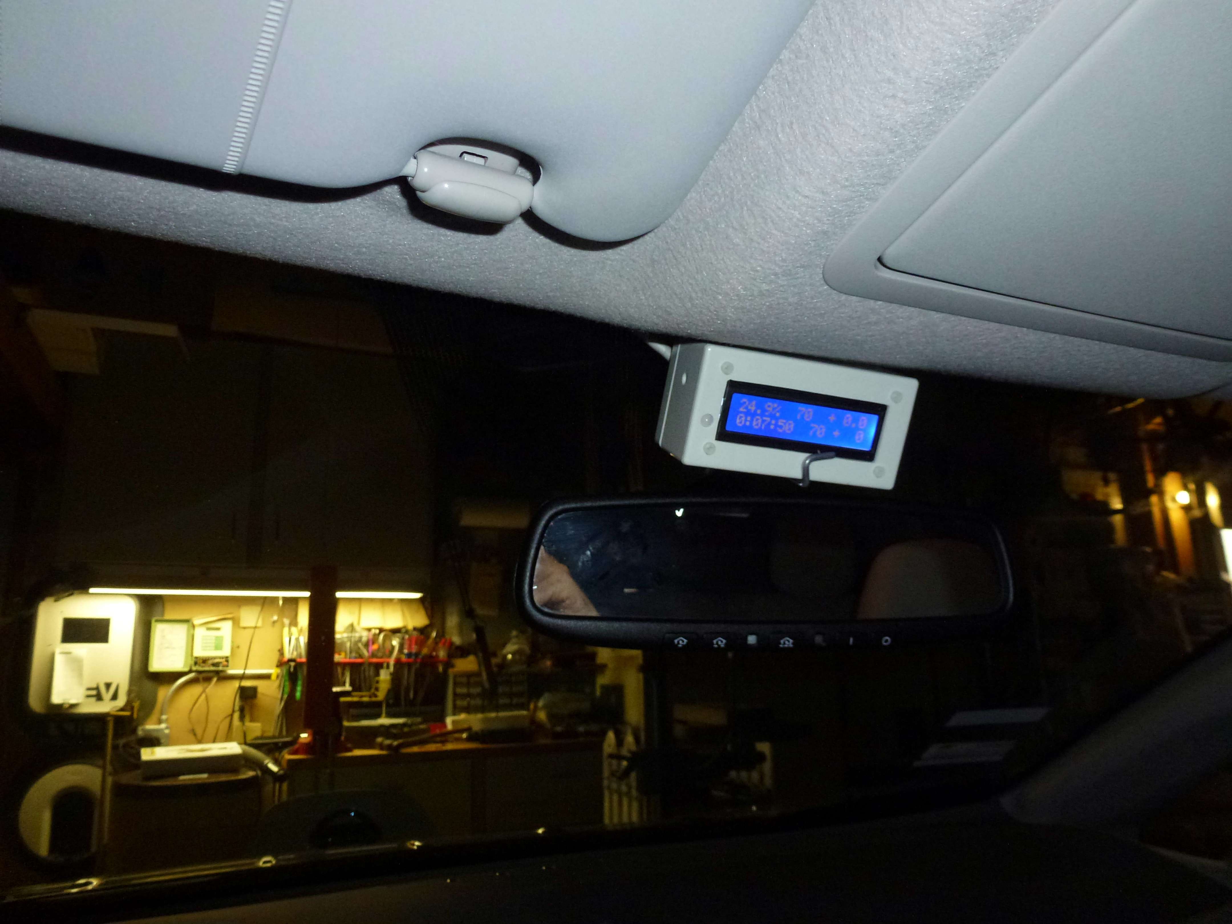
Here is the mounted display being tested to see what it will look like. It is still driven by the small test board. Note the attached SX-Key to the right of the test board.
Here is a little overview of the Code.
The interrupt routine runs every 2 usec or every time a CAN falling edge is detected. The falling edges are used to resync the 2 usec timer to keep it locked to the CAN Frames. The interrupt routine first looks to see what caused the interrupt. If it was a clock edge it resyncs the 2 usec timer and exits. If it was the 2 usec timer then it checks to see if it is time to shift a bit out the serial port. At 57,600 baud a bit is shifted out every 26 usec so every 13 timer interrupts (13 x 2 usec) a bit could be shifted out if there are any waiting. After that the code handles the CAN bit. The serial port plus CAN bit code must total less than 100 instructions for this to all work and fortunately it fits.
The main code handles processing the next completed and good (CRC ok) CAN Frame that is waiting in one of the two buffers. It first filters based on Frame IDs which to dump to the serial port (5BC for now) and loads each byte into a send buffer and waits for it to be sent. After all the data is dumped the main code updates the 2x16 display based on what is in the CAN Frame buffer and when done marks the CAN Frame buffer empty and start over again when the next frame buffer is full.
Over the next few days I plan to build the final version of the board that plugs into the display and mount it and the switching power supply in the project box and wire in the CAN Cable. (Or it might be delayed a week or two due to an upcoming trip to Ireland.)
The CAN Cable is the most expensive part followed by the display, SX28AC and MCP2551 Transceiver. I don’t have a cost for 12v to 5v power supply since they came with some old phones.
With the switcher power supply I measure only 60 milliamp at 12 volts used to run the logic and drive the display. The SX28AC also supports a sleep function that may have some use do reduce the power rather than turn it off. If I can get the hardware to sleep rather than power off I could save data from one power/charge cycle to another. That could be of some use to display summary type information.
(Updated to include pricing table 2/23/13)
Here is the current price list.
If you are interested in getting a WattsLeft™ please email to [email protected]. I can send you a copy of the Quick Guide to show you what information can be displayed on the 15 selectable screens. Jump to bottom of Page 8 for lastest information.
I recently acquired some surplus Parallax SX28AC chips in DIP packages. After looking at the datasheet it seemed likely I could design an entire SOC meter around this single chip processor. As a result I took the leap and purchased an SX Key (USB) board which allows programming and in-circuit source-level debugging as well as some 50 MHz three pin resonators all from Parallax.
The SX28AC is a very basic single chip system with 2K words (12 bits) of EEPROM program storage, 136 bytes of RAM all inside a 28 pin package with 20 general purpose I/O pins. The instruction set is similar to the PIC16C5x series but with a few more instructions. It can run at up to 75 MHz with one instruction executed each cycle (except for jumps/calls, of course).
Here is the pin list.
Here is a summary of the instruction set.
The clock rate for this project was selected to be 50 MHz so there would be 100 instructions executed per CAN bus bit (2 usec per bit). This seemed like it would give enough time to handle all the processing plus support a 57,600 baud serial out link to dump CAN frames to a PC.
There are no peripheral functions built-in like a CAN processor or Serial ports. It has only an 8-bit Real Time counter and a single Analog Comparator that can be selected to take over two of the 20 available I/O pins.
The original plan was to use only the SX28AC and a display. To do this I planned on using the Analog Comparator with one side connected to the CANH line and the other to a resistor divider set at a 3 volt level. I was not sure how well this would work since the idle level is 2.5 volts and dominant level is 3.5 volts. So for initial development I decided to remove this variable and just go with a standard MCP2551 CAN Transceiver. Once all the code is debugged and working I may go back and remove the MCP2551 and add the resistor divider.
Below is what the first test board looked like. The 5 volt power is from an old car cell phone charger I had laying around. The black and orange wires are the Serial out lines which go to a 9 pin D connector. Most serial ports accept TTL level so you don’t need a converter to give +/- 12 volt levels. I am using a Serial to USB adapter with my laptop. The connector on the right with three pins is from the CAN cable. The blue dot is the 50 MHz resonator and the single button is for reset. Decoupling caps are under the ICs. The four pins on the left go to the SX-Key for programming/debugging.
Here is a dump from the serial port of the raw SOC CAN messages including CRC. The code handles all the CAN bit processing (de-stuff, Serial to Byte, and CRC checking). Only messages with good CRC are passed on for processing. The code has two CAN Frame buffers so one can be processed by the main code loop for display/serial dump while the other is being filled in by the interrupt driven receive routine. Flags prevent overrunning the buffers. CAN frames that come in while both buffer are full are skipped.
A 2 line by 16 character LCD display was selected to display the data to the user. The displays only cost $3.99 each including shipping.
Here is the test board connected to the LCD display. There is a 10k pot sticking up to adjust contrast. With two lines of 16 characters there is room to show lots of information. This code version is showing SOC Percent, Gids number (my daughter wanted the 281 added to indicate the max value. The second line starts with the CAN Frame ID for SOC 0x5BC. Next I added trip/charge gauge. In this case it is showing the number of Gids that it took today to charge our Leaf back up to 80% (actually 82.2%, Blink said 3181 watts were used). While driving the number will be negative and show Gids used since the meter was powered on (car turned on).
The hardware I have built so far is just for testing to allow debugging of the code. Here is the box that will hold the final version of the hardware which will plug directly into the display pins (no orange jumper wires). The cover has already been cut and display mounted. The 5 volt switching supply is shown laying in the bottom of the box. The box is 4 3/8 by 2 7/16 by 1 1/8.
Here is the mounted display being tested to see what it will look like. It is still driven by the small test board. Note the attached SX-Key to the right of the test board.
Here is a little overview of the Code.
The interrupt routine runs every 2 usec or every time a CAN falling edge is detected. The falling edges are used to resync the 2 usec timer to keep it locked to the CAN Frames. The interrupt routine first looks to see what caused the interrupt. If it was a clock edge it resyncs the 2 usec timer and exits. If it was the 2 usec timer then it checks to see if it is time to shift a bit out the serial port. At 57,600 baud a bit is shifted out every 26 usec so every 13 timer interrupts (13 x 2 usec) a bit could be shifted out if there are any waiting. After that the code handles the CAN bit. The serial port plus CAN bit code must total less than 100 instructions for this to all work and fortunately it fits.
The main code handles processing the next completed and good (CRC ok) CAN Frame that is waiting in one of the two buffers. It first filters based on Frame IDs which to dump to the serial port (5BC for now) and loads each byte into a send buffer and waits for it to be sent. After all the data is dumped the main code updates the 2x16 display based on what is in the CAN Frame buffer and when done marks the CAN Frame buffer empty and start over again when the next frame buffer is full.
Over the next few days I plan to build the final version of the board that plugs into the display and mount it and the switching power supply in the project box and wire in the CAN Cable. (Or it might be delayed a week or two due to an upcoming trip to Ireland.)
The CAN Cable is the most expensive part followed by the display, SX28AC and MCP2551 Transceiver. I don’t have a cost for 12v to 5v power supply since they came with some old phones.
With the switcher power supply I measure only 60 milliamp at 12 volts used to run the logic and drive the display. The SX28AC also supports a sleep function that may have some use do reduce the power rather than turn it off. If I can get the hardware to sleep rather than power off I could save data from one power/charge cycle to another. That could be of some use to display summary type information.