Hi, I will try to describe in detail how to force the ac-dc converter to work.
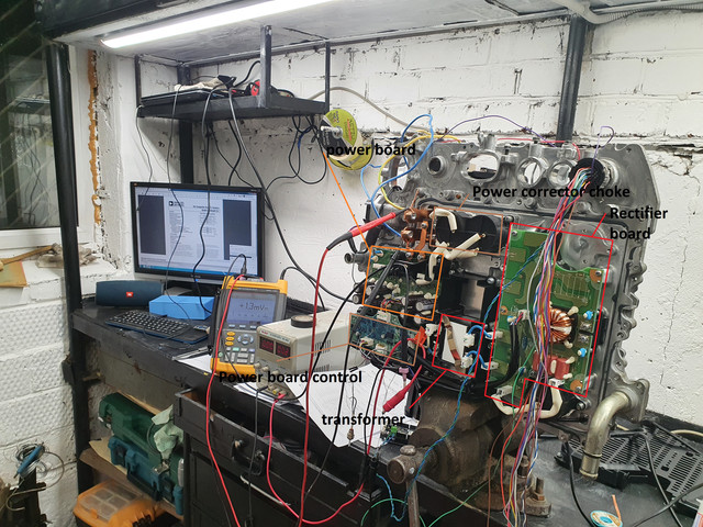
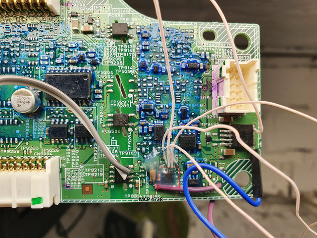
The first photo shows a general plan of the rear of the PDM.
For a successful launch, we need to modify the power control board.
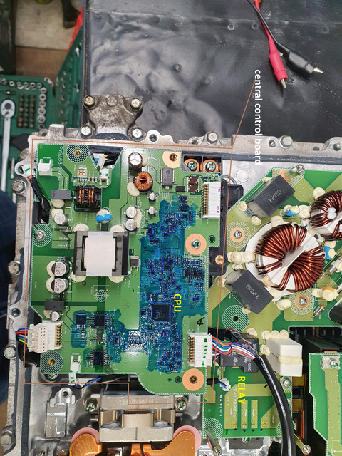
The second photo shows the main control board of the PDM, it is located in the upper part.
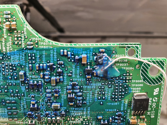
We remove the power control board and do the revision from the back. We solder the conductor to the gate of the field-effect transistor, an example in the third photo. If you pull it to the ground then the power corrector starts and the relay is turned on to supply alternating current to the rectifier bridge. CAUTION Do not apply AC power while the relay is on. you can turn on the power corrector only after preliminary charging the capacitors of the power corrector (this happens automatically through a powerful 10 ohm resistor when the AC is turned on)
Now we start the PWM. The fourth photo shows the revision for starting, in the same way we solder the conductor if it is pulled to the ground, the PWM will start, but there will be no pulse generation on the UCC2895 chip due to the fact that there is no voltage at the input of the error amplifier, it should be higher than 3.6 volts. Look at contact 20.
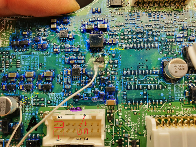
I ask you not to pay attention to the many wires, I was experimenting)
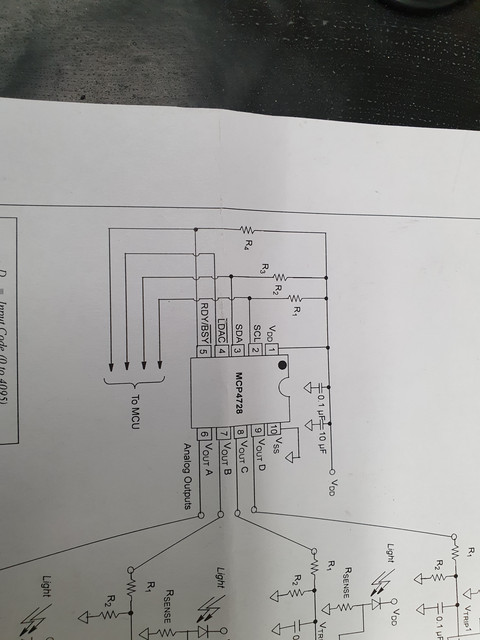
The fifth photo shows the refinement in order to start the generation of pulses and successfully control the output current.
We need to raise the 6th pin of the MCP4728 microcircuit and solder the conductor to the printed circuit board for the 6th pin and be sure to output GND, since the unit is galvanically isolated from the power key control board.
Now when we supply voltages from 0 to 4 volts, we will change the current of our converter.
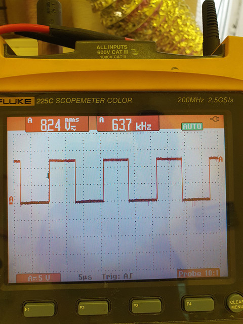
If everything is done correctly, we will see the generation of pulses on pin 18 of the UCC2895 microcircuit as shown in photo # 6
INCLUDING ORDER
1. Turn on + 12V in a regular way according to the documentation.
2. Directly supply alternating current of 220 volts
3. Turn on the power corrector (tightening on gnd)
4. Turn on the PWM (tightening on gnd)
5. We supply power to the feedback (6 pin of the printed circuit board on the seat of the MCP4728 microcircuit.
MY THOUGHTS
You can control the MCP4728 using I2C, there is a library in the arduino network) As I understand it, the inverter uses only 1 channel if you apply 4 volts, the inverter will work at full power.
In normal use, the processor gives a command via the I2C interface and the MCP4728 generates a voltage from 0 to 4 volts on channel a. I have not finished the hardware study of the inverter yet, but I'm sure that current and voltage readings are coming to the CPU!
In my project e-baggi will be able to power the consumer with a PDM with a voltage of 220 volts DC from the main battery) and charge too!
Good luck everyone and be careful with high voltage !!!!!!


") .
.