
You are using an out of date browser. It may not display this or other websites correctly.
You should upgrade or use an alternative browser.
You should upgrade or use an alternative browser.
Onboard charger capacitors failed
- Thread starter sujeeva
- Start date
Help Support My Nissan Leaf Forum:
This site may earn a commission from merchant affiliate
links, including eBay, Amazon, and others.
This thread has been quite helpful, thanks!
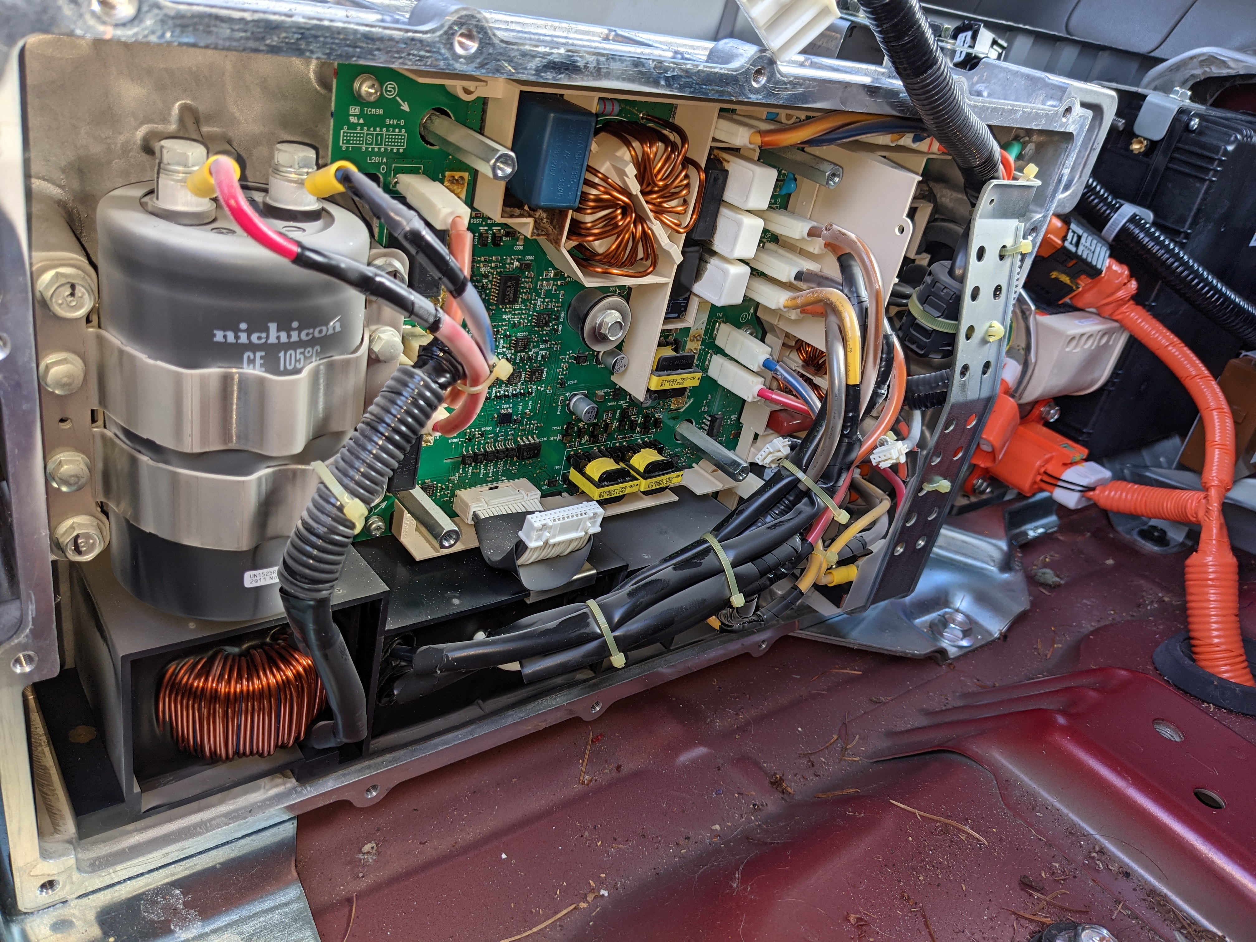
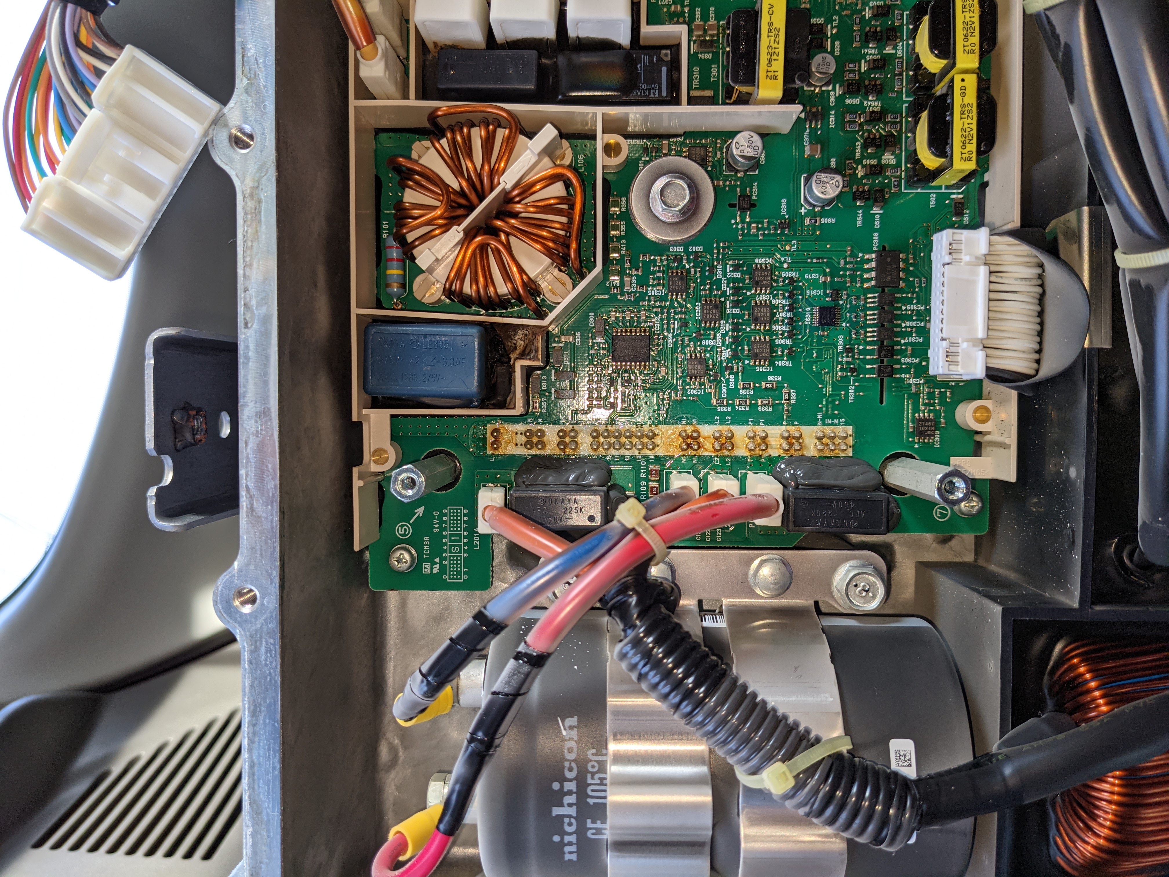
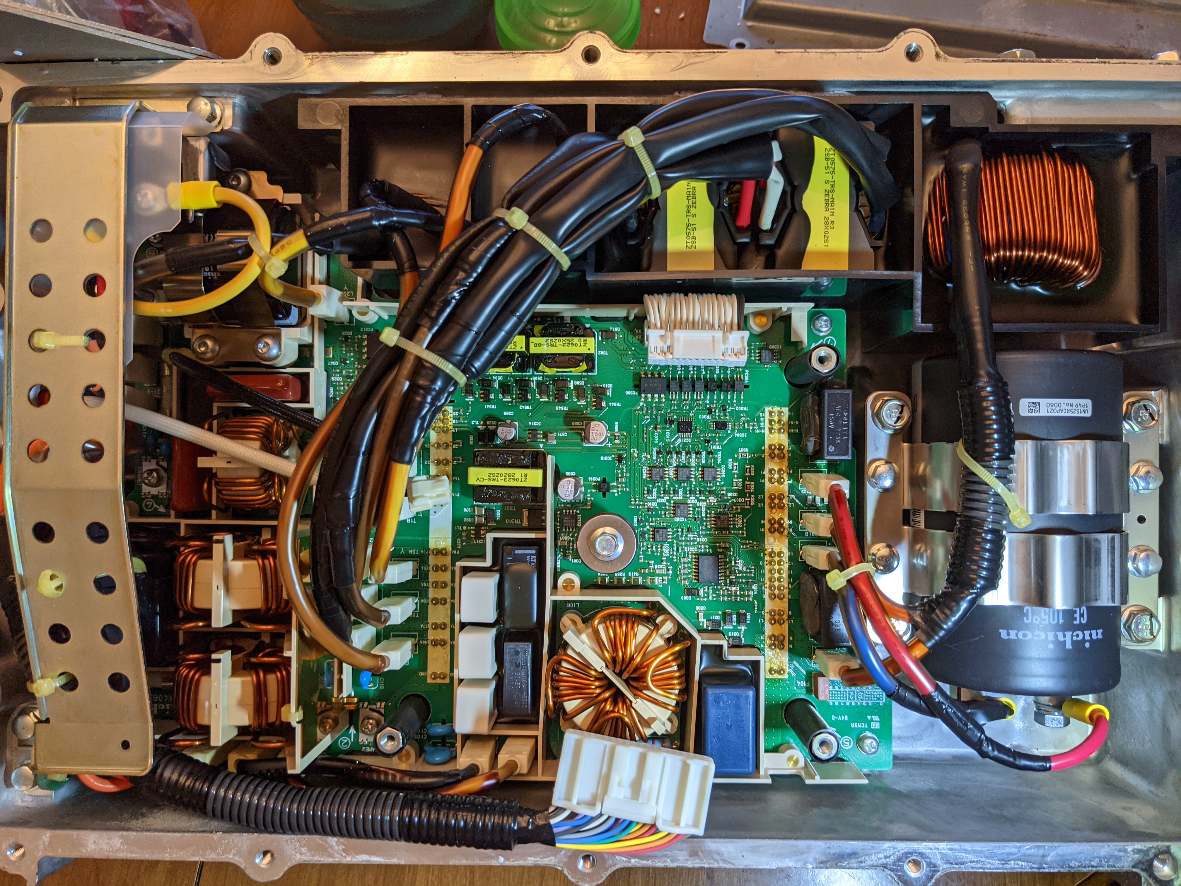
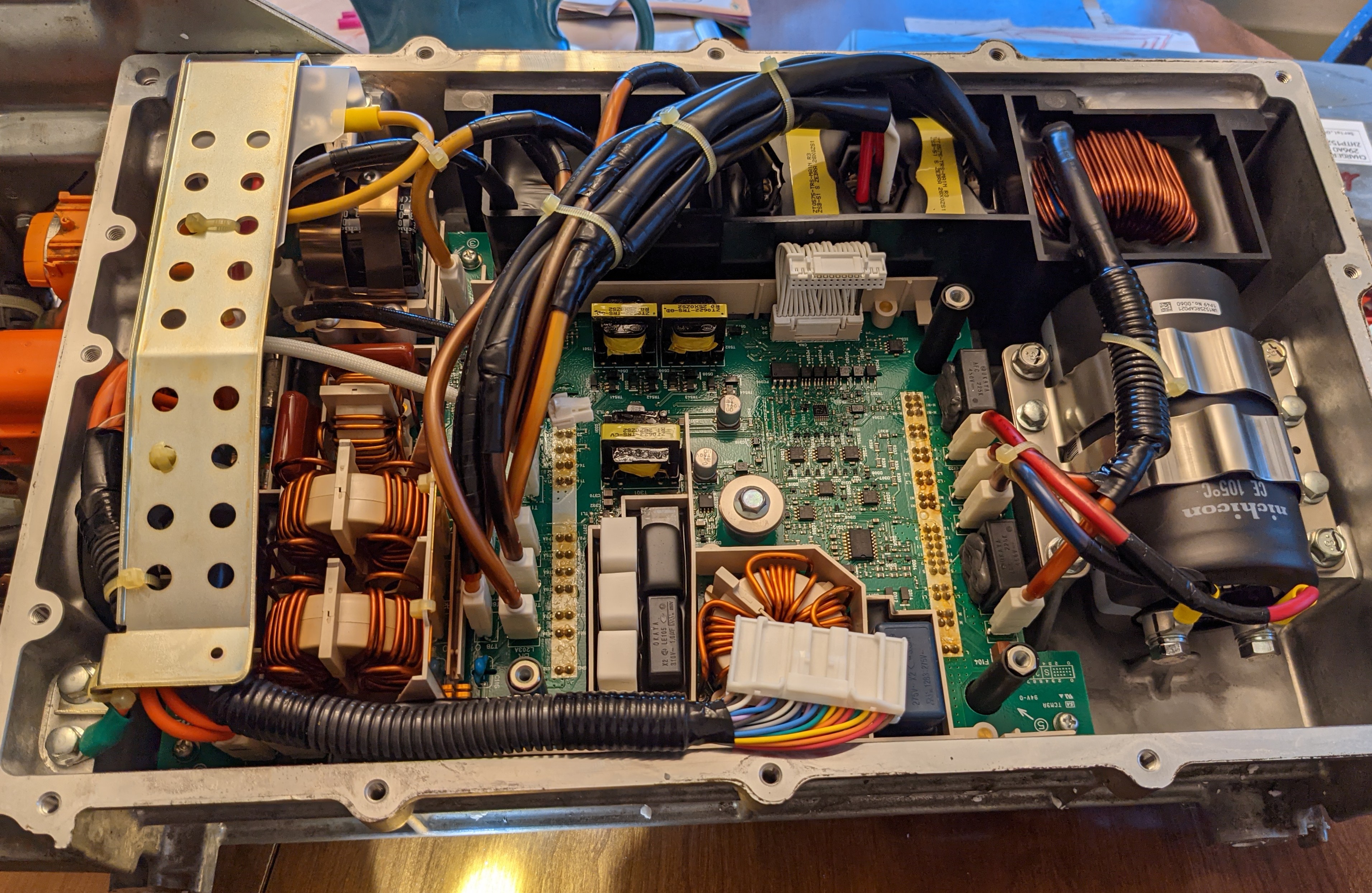
I just purchased a 2012 Leaf, CHEAP, with a bad charger. Looks like it has at least 1 fried suppression cap, that coated the entire inside of the charger with magic smoke residue. I'll dig in farther and post more pictures soon.
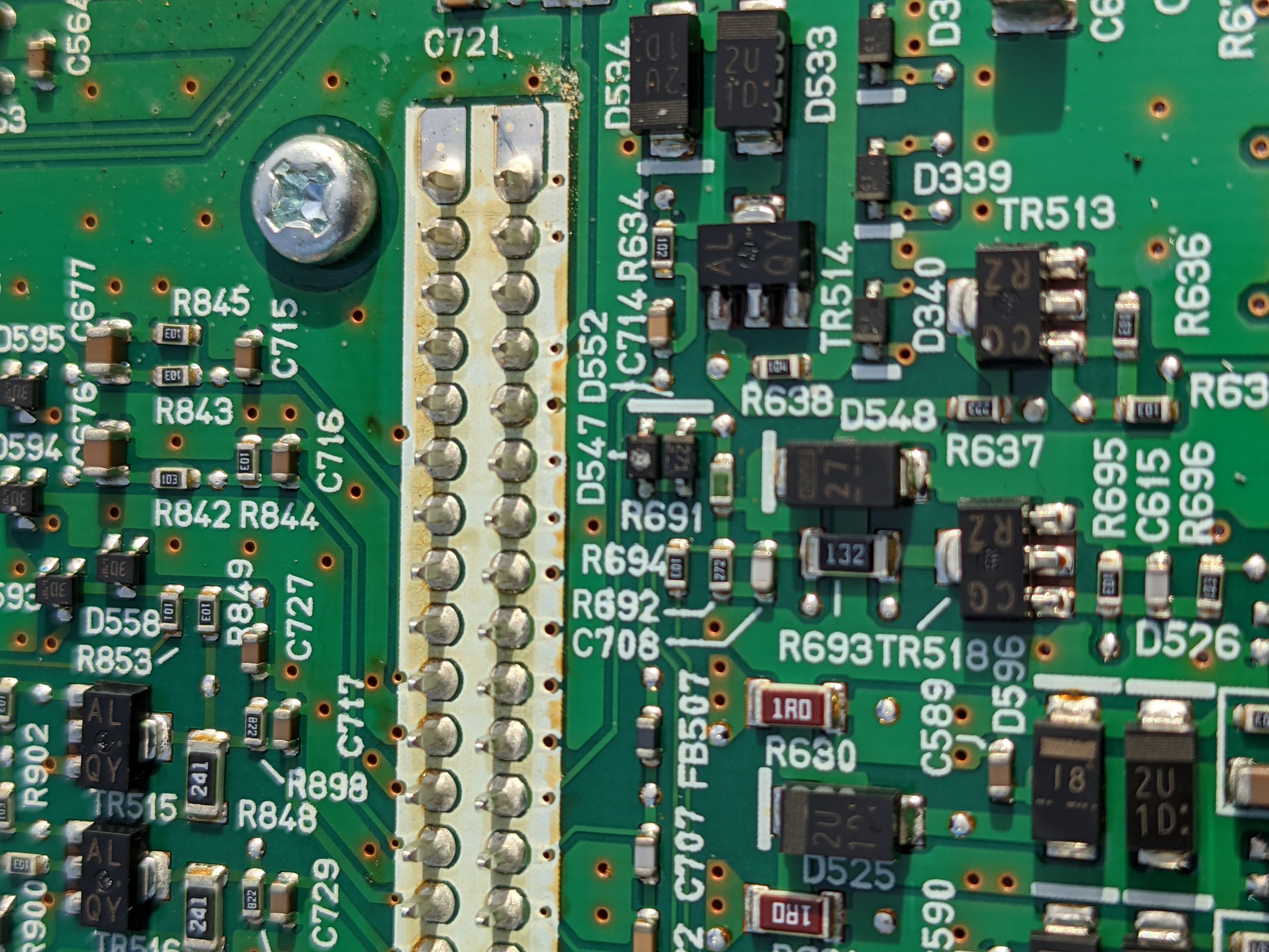
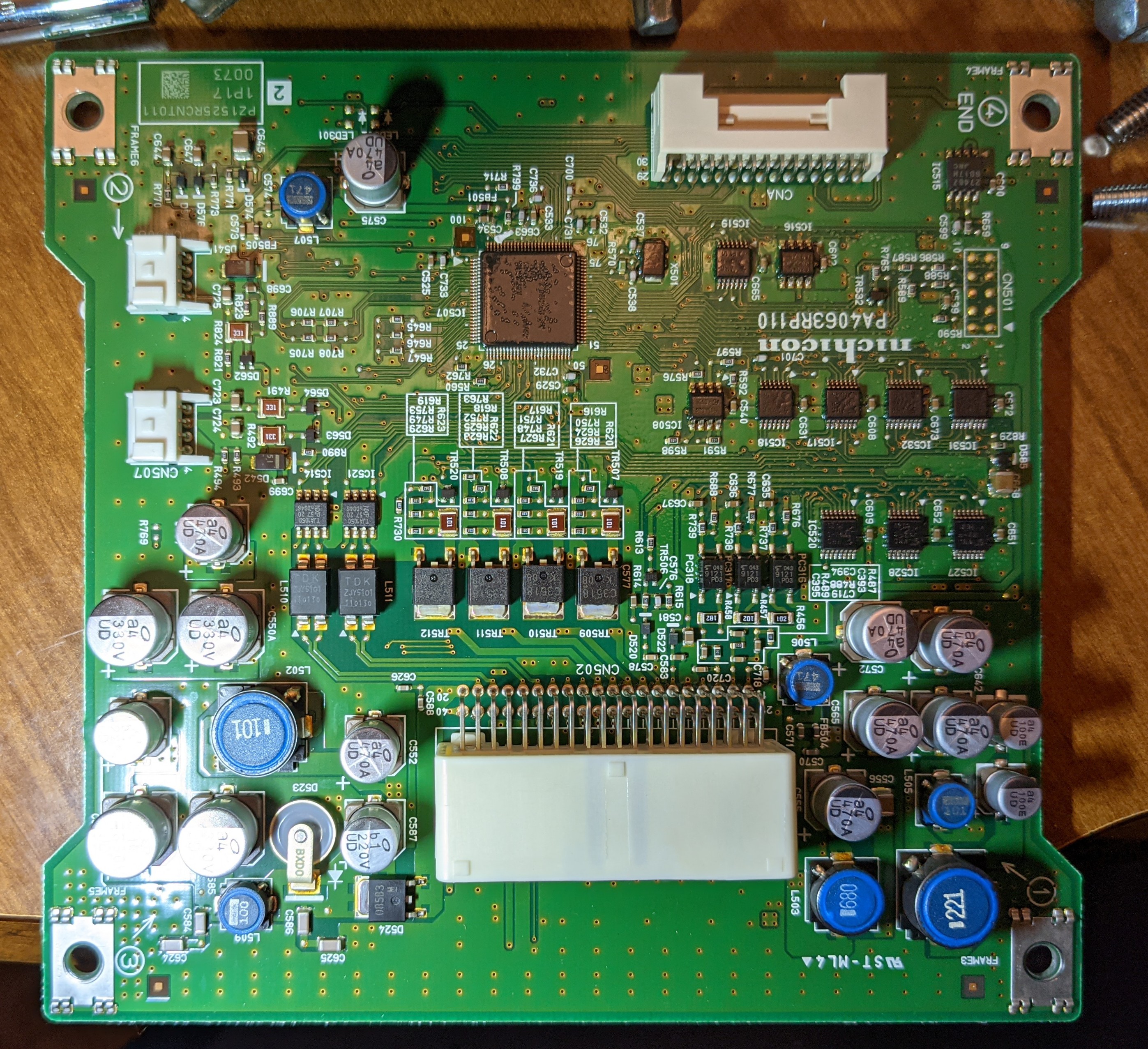
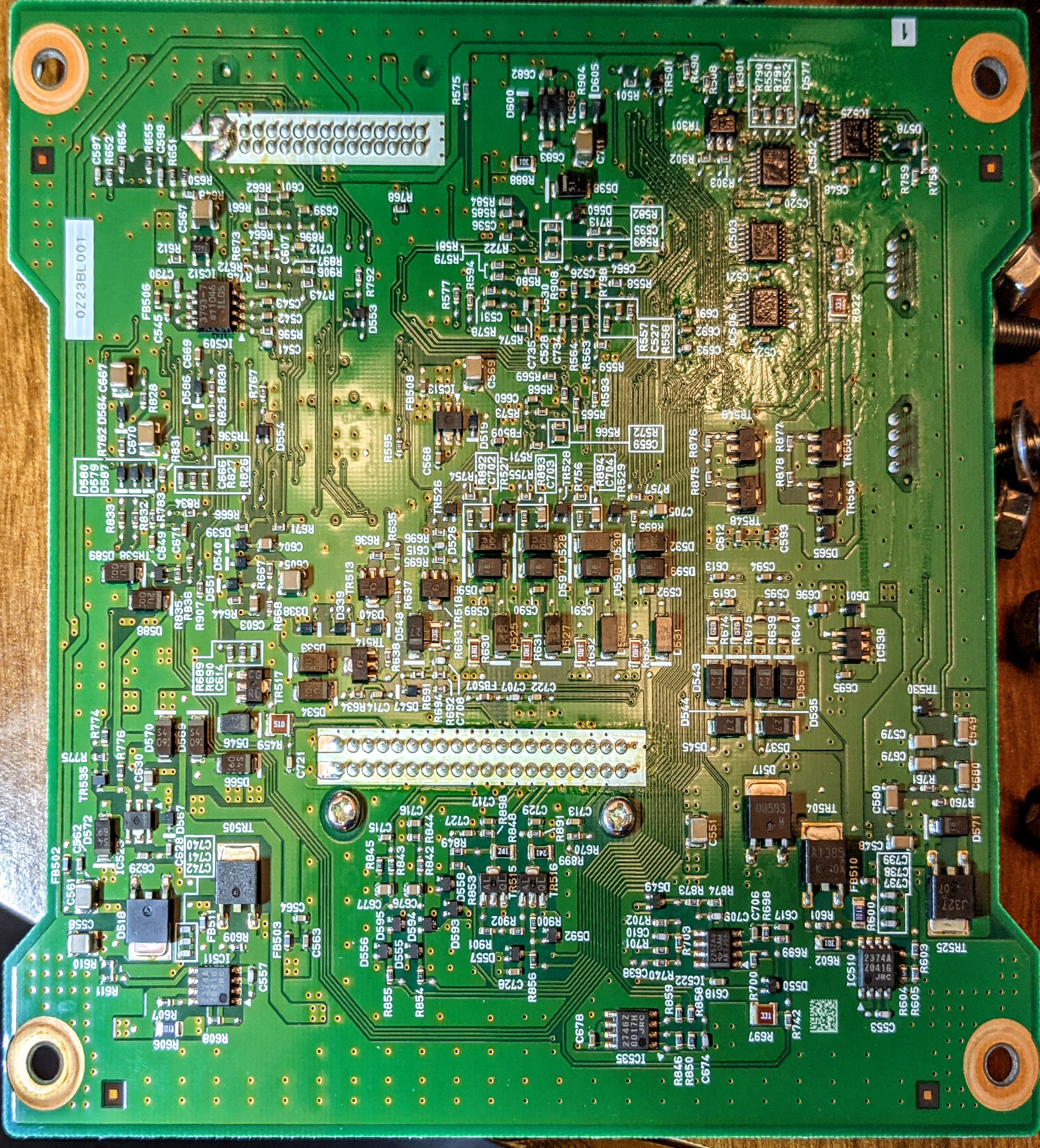
On the top board, D547 looks a little toasted, but tests okay.
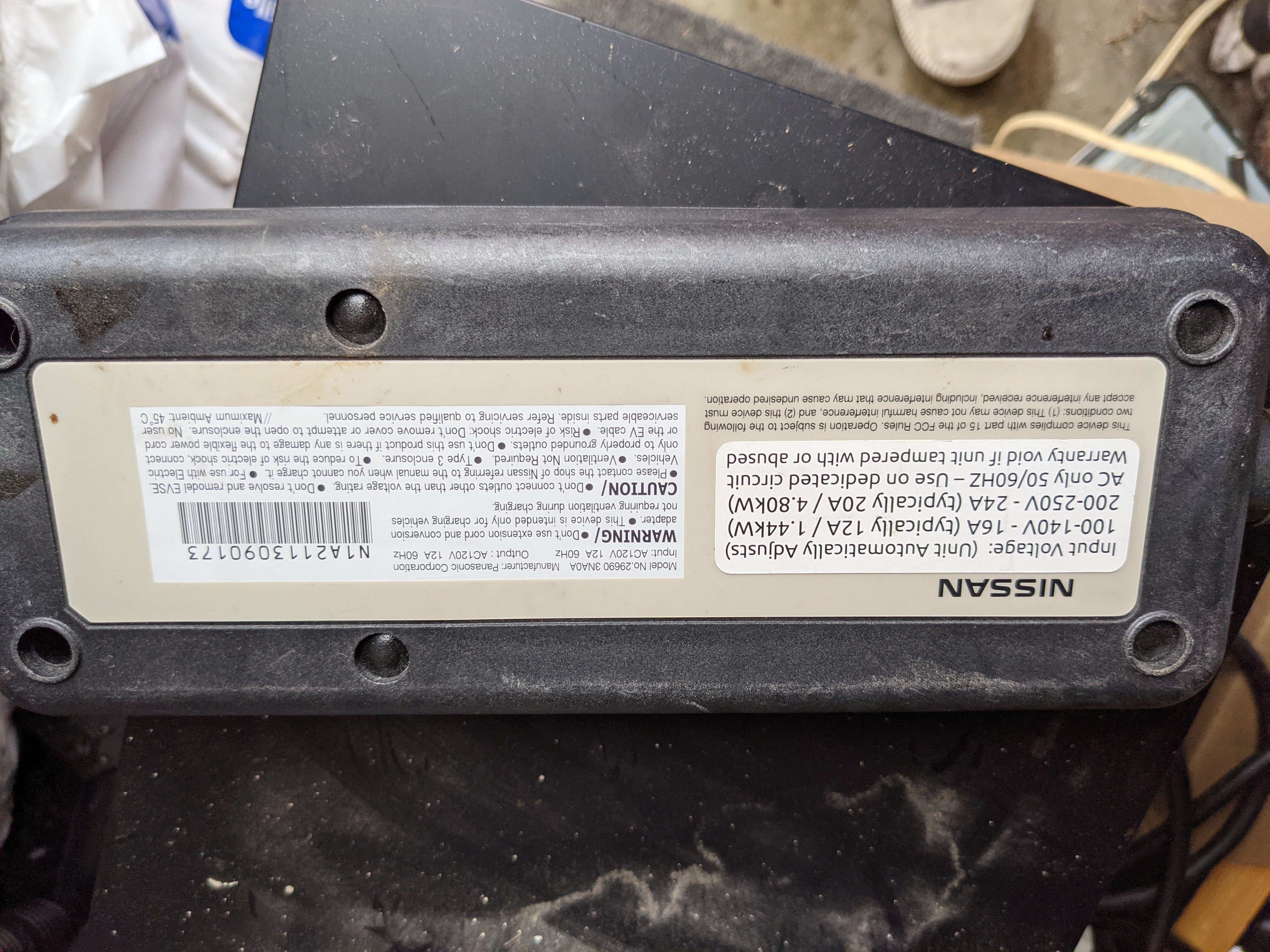
Oh, and the OEM charger appears to have been upgraded to 240 volt capability. Any idea if this is reliable?
I just purchased a 2012 Leaf, CHEAP, with a bad charger. Looks like it has at least 1 fried suppression cap, that coated the entire inside of the charger with magic smoke residue. I'll dig in farther and post more pictures soon.
On the top board, D547 looks a little toasted, but tests okay.
Oh, and the OEM charger appears to have been upgraded to 240 volt capability. Any idea if this is reliable?
It has been a couple of months so I guess I should update:
To this point, the on board charger with the replaced capacitors and the swapped cooling components is continuing to perform as expected without errors. The car charges, and let’s be honest, that’s enough!
In order to guarantee that my EVSE didn’t cause the components to fail (assuming that could’ve been the original culprit), I replaced my EVSE with a second hand, excellent condition Aerovironment. So far, so good.
A huuuge thanks to everyone (especially @nlspace) for all of your help! It took a lot of time, and effort, but it brought my LEAF back to life.
91040
Well-known member
Your EVSE looks like it was modified by EVSE Upgrade. They did quality work but I would test it given your onboard charger was blown.
Who1981 said:Oh, and the OEM charger appears to have been upgraded to 240 volt capability. Any idea if this is reliable?
91040
Well-known member
Sorry but I am not qualified to offer any technical advice.
The J1772 standard is published. OpenEvse.com had a page which showed and discussed it. They also had a schematic for a small board to check whether the EVSE conformed to the standard.
There are also threads on this forum that discuss EVSEs and their problems. Hopefully, a knowledgeable person will soon weigh in. Good luck!
Link to J1772 basics- https://openev.freshdesk.com/support/solutions/articles/6000052074-basics-of-sae-j1772
Testing an openevse may provide some insights-
https://openevse.dozuki.com/Guide/Testing+Basic+and+Advanced/12?lang=en

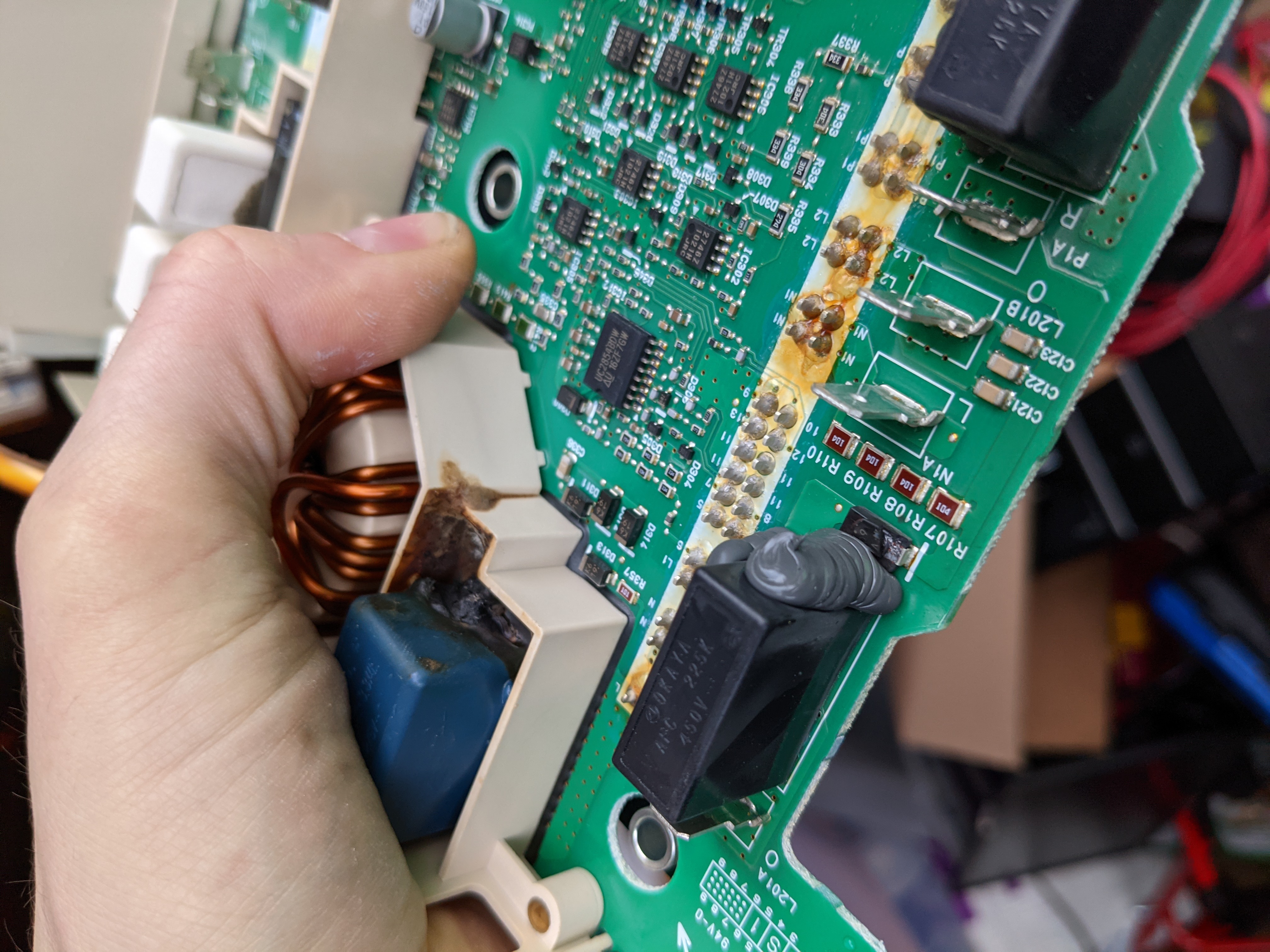
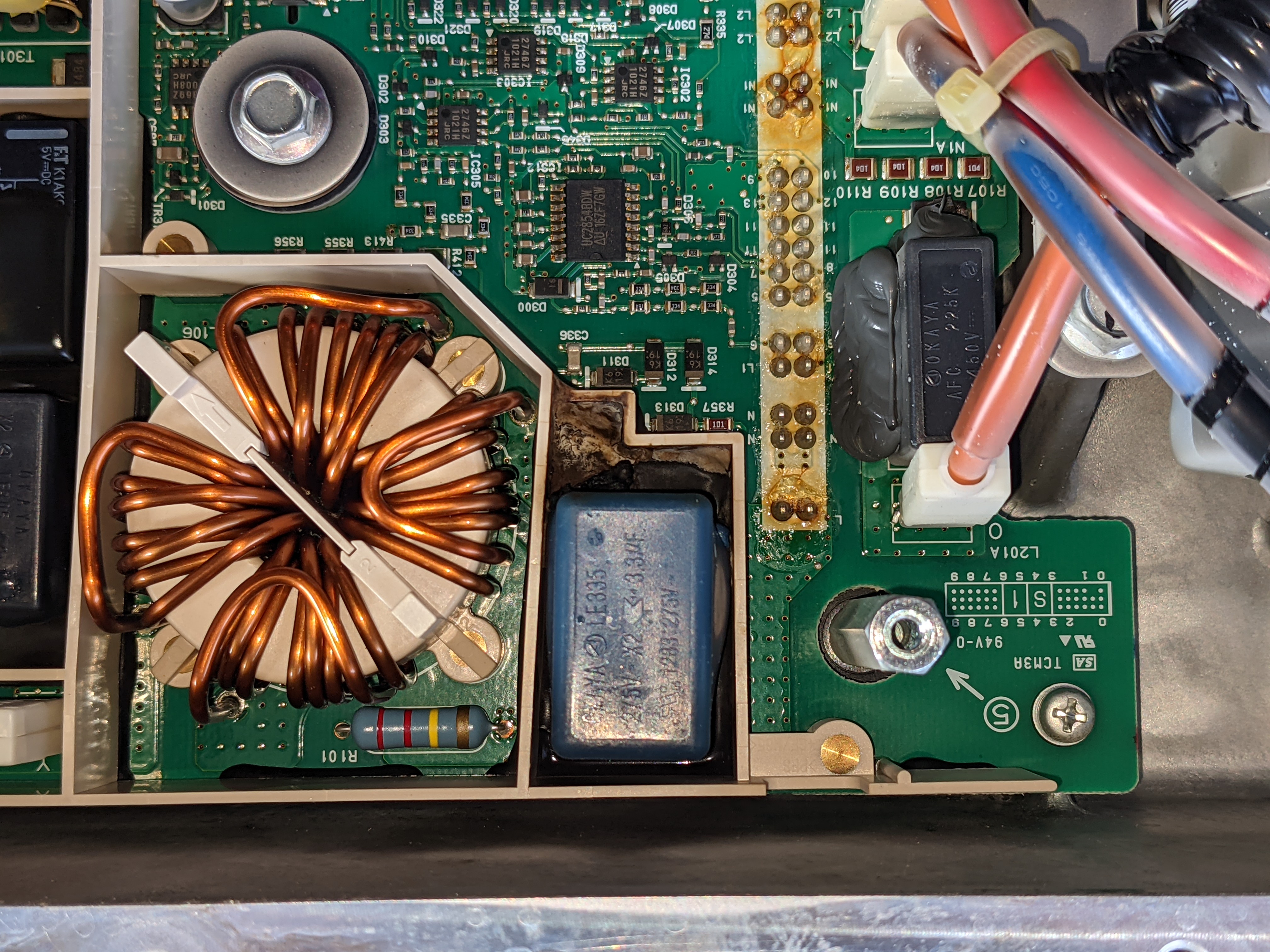
Those are all on the AC input side of the OBC, so that is actually a good thing in that replacement can be made on those parts to repair the unit.
Was the OBC already defective when you got the car? This didn't happen by you plugging in the EVVSE to chargge the car?
What was the reference designator of the fuse--like F101, etc?
Was the OBC already defective when you got the car? This didn't happen by you plugging in the EVVSE to chargge the car?
What was the reference designator of the fuse--like F101, etc?
I bought the car cheap with the charger already not working. The previous owner just said it stopped charging in the middle of the night. It was on this evse that has been modified.
F101 is blown.
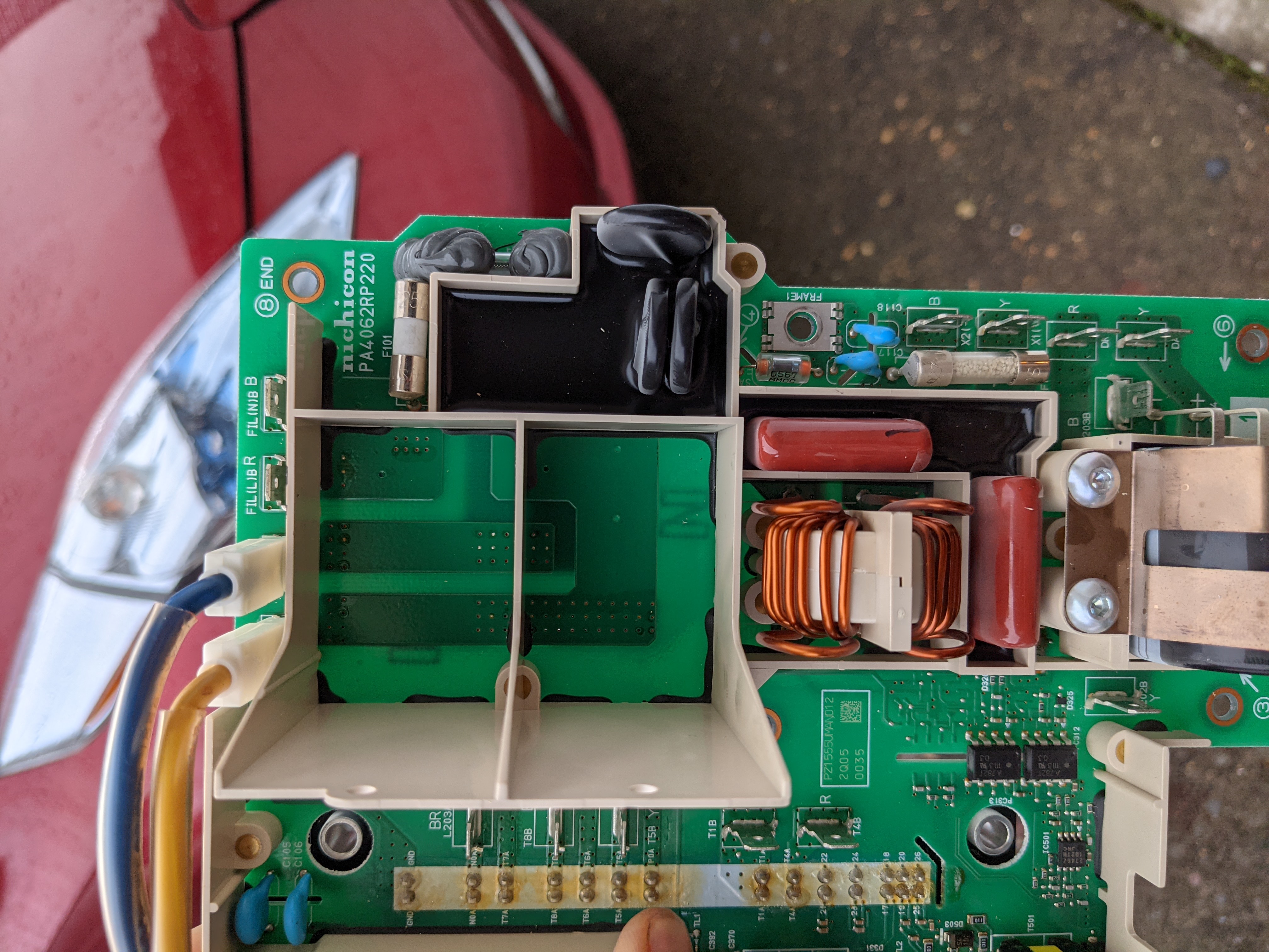
The other capacitor I found might be even trickier to remove with the waffle plate in place. If I do try to repair this board, I'll be getting some good desoldering practice.
F101 is blown.
The other capacitor I found might be even trickier to remove with the waffle plate in place. If I do try to repair this board, I'll be getting some good desoldering practice.
You should probably check the diode drops of the waffle plate to make sure that it is not shorted/damaged, especially the AC rectifier section and the PFC.
With all the damage on the AC input side it is puzzling what might have caused this, similar to wxmatt's damage.
With all the damage on the AC input side it is puzzling what might have caused this, similar to wxmatt's damage.
The black potting material is soft and flexible. It is easily removed with a wooden scraper made out of a bamboo chopstick, sharpen one end like a pencil for fine work and whittle the other end to a flat blade like a screwdriver.
The gray RTV material is more rigid but still flexible. The bulk of it can be carefully sliced and cut with a sharp blade, then use the wooden scraper to get the thin remains off the board. don't try to cut right at the board with the steel blade--don't want to damage the board.
The gray RTV material is more rigid but still flexible. The bulk of it can be carefully sliced and cut with a sharp blade, then use the wooden scraper to get the thin remains off the board. don't try to cut right at the board with the steel blade--don't want to damage the board.
Thanks, good tips. I'll source the parts and start in on it.
I got the eBay charger in. It was a little dirty outside, and smelled slightly hot inside, but other than a couple discolored wires has no signs of failure. I clamped off the coolant lines and swapped in the charger with minimal mess. And it works on 120V and 240V! Charged fully, and drove the Leaf to work today.
I got the eBay charger in. It was a little dirty outside, and smelled slightly hot inside, but other than a couple discolored wires has no signs of failure. I clamped off the coolant lines and swapped in the charger with minimal mess. And it works on 120V and 240V! Charged fully, and drove the Leaf to work today.
hannesbeukes
Member
- Joined
- May 23, 2021
- Messages
- 7
Well done, and thank you for all the information and the photos.
I have also opened my obc but i left it in the car without removing the coolant lines,
You can pretty much disconnect the main hv connector on the floor and then open the charger lid and work on it without removing it from the car.
I have also opened my obc but i left it in the car without removing the coolant lines,
You can pretty much disconnect the main hv connector on the floor and then open the charger lid and work on it without removing it from the car.
hbquikcomjamesl
Well-known member
- Joined
- Mar 1, 2021
- Messages
- 208
Glad you got it working. And fascinating pictures.
Seeing the thread title reminded me of something that had happened many years ago. I'd installed a lighted street address sign on my house, powered by the doorbell transformer, and I'd fitted it with a photocell, using a circuit that required a rectifier and a filter capacitor.
Then I bought a new doorbell, that required a higher voltage transformer. Higher than the WVDC rating of the filter capacitor. Significantly higher
When I turned on the power, I heard a loud bang. A short time later, I found the capacitor casing in a flower bed, along with the foil and fibrous material that had formed the innards of the capacitor. And a few shards of plastic where the capacitor had blown a hole in the side of the sign.
Oops!
haloo from georgia.
my country is near from the russia.
we have some Nissan Leaf in owre country.
I have problem with obc onboard charger on nissan leaf 2011 year.
problem is that my home charger not charges vehicle. i have other home charger, it do same.
we have not good repairmans, one of them says thet onboard charger that is back in the car is bad, i changed it myself. vehicle warks good. but i want repair old OBC block.
if anyone can tell me, from what i bigin repairings. whare i can search problems in onboard charger?
i allready open the cover off.
Top (Control) Board seems very well. there is not eny problems that i can see.
please halp me to search the problem in this OBC block.
my english is not so good as I want, excuse me for this.
Sorry for my poor English.
Can you post some photos of your boards?
What is your level of knowledge, skills and abilities related to electronics repairs, soldering, use of a DMM, reading schematics and tracing circuits on a board, etc.? This would be helpful to know before digging into a repair.
What is your level of knowledge, skills and abilities related to electronics repairs, soldering, use of a DMM, reading schematics and tracing circuits on a board, etc.? This would be helpful to know before digging into a repair.
nlspace said:Can you post some photos of your boards?
What is your level of knowledge, skills and abilities related to electronics repairs, soldering, use of a DMM, reading schematics and tracing circuits on a board, etc.? This would be helpful to know before digging into a repair.
My knowladge is not so low level. I can diagnos capasitors, resistors, diodes, transistors.
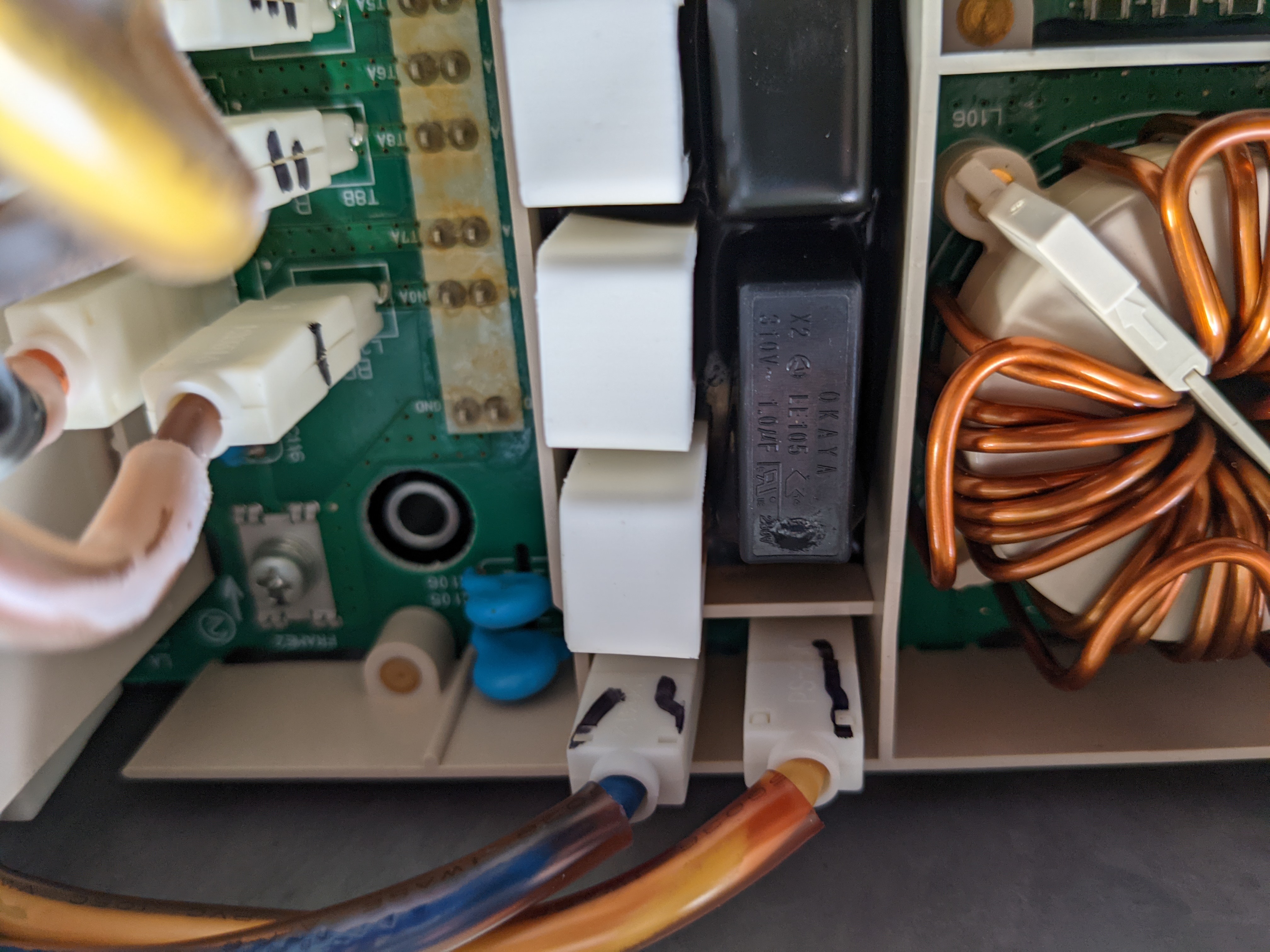
I have not photos. But i find visual deffects, there is hol on the capasitor. Capasitor 310 v 1.0 mf near the big 3 resistors is bad.
It is nesesery to desolder the waffle plate to change the capasitor. I have 400 v 1.0 mf capasitor. Can i replace the 310v 1.0 mf capasitor with 400v 1.0 mf?
And last question,
if i do not desolder the waffle plate i can change thet capasitor but it need small cables for contacting thet pins where it must be. There is black maaterial arrround the capasitor, relay and resistors, can i replace thet material with wbhite silicon?
If anyone can post me the schenatics of this obc i wil be happy.
My mail :. [email protected]
thank you for help.
the black potting comes off easily with a wooden scraper. don't use a sealer that releases acetic acid as it cures.
A higher voltage capacitor is okay as long as it is the same type. See my post on page 1 of this thread.
for what part of the circuit are you wanting a schematic? There is not one for the entire OBC as far as i know.
There is lots of troubleshooting discussion in this thread that might give you some help.
Similar threads
- Replies
- 8
- Views
- 3K
- Replies
- 13
- Views
- 6K
- Replies
- 9
- Views
- 2K
- Replies
- 14
- Views
- 4K
Latest posts
-
-
-
-
The Definitive "CLICKING NOISE FROM FRONT OR REAR AXLE DURING TAKE-OFF/ACCELERATION" list
- Latest: KeepTheCoalInTheHole
-
-