OpenEVSE - Open Source Charging Station

My Nissan Leaf Forum

Help Support My Nissan Leaf Forum:

This site may earn a commission from merchant affiliate links, including eBay, Amazon, and others.
Yeah, The meters are amazingly inexpensive. When I first purchased one I thought $18 was a good deal. Now you can buy them for around $10 shipped.

They work well and I have had no failures in service. I did burn one up since they switched connections and I did not notice.
 
$9.99, with free shipping from the other side of the world. How can they do it?

Do you think they are safe, accurate and reliable?
 
I have measured the voltage and current on several units. On resistive loads they are very accurate. With the modified sine wave of my leaf the current was about .5A low compared to my RMS clamp on meter. They have 2 pots, one for voltage and one for current. I simply adjusted the current one to match.

I do not know how accurate the RAV4 EV charger is but it said 31A using my Leaf calibration while charging Pchilds RAV. I do know from measuring it that the Leaf is not a quite a proper sine wave.

Some of the Chinese prices are amazing. The USBASP programmer Chris sells for $20 is less than $3 shipped. The USBTinyISP that was around $20 is now about half of that now. Everything except one $3 item has worked so far. I also do not know how they do it. It would cost me more to return the broken item than I paid for it.

As to how safe they are, I have had no failures. On my EVSE and the one I have for sale, the MOVs are fused and the meter is connected after the fuses. This protects the wiring from a meter problem. If the meter does not work them one of the fuses may have blown.
 
z0ner said:
You can buy them cheaply on eBay, but shipping may take some time since they're all coming from China/Hong Kong: http://www.ebay.com/sch/i.html?_trksid=p2050601.m570.l1313.TR0.TRC0.H1.X240V+dual+volt+amperage+meter&_nkw=240V+dual+volt+amperage+meter&_sacat=0&_from=R40" onclick="window.open(this.href);return false;
Do those cheap meters account for power factor? It it showing reactive amps or resistive amps? From Glenn's comment it sounds like they are only good for measuring resistive loads?
 
drees said:
z0ner said:
You can buy them cheaply on eBay, but shipping may take some time since they're all coming from China/Hong Kong: http://www.ebay.com/sch/i.html?_trksid=p2050601.m570.l1313.TR0.TRC0.H1.X240V+dual+volt+amperage+meter&_nkw=240V+dual+volt+amperage+meter&_sacat=0&_from=R40" onclick="window.open(this.href);return false;
Do those cheap meters account for power factor? It it showing reactive amps or resistive amps? From Glenn's comment it sounds like they are only good for measuring resistive loads?
These meters report only the voltage and ampere. It says nothing about power consumption.
But in any case, the PF of the OpenEVSE is very close to 1, as measured by my TED 5000.
 
greenleaf said:
drees said:
z0ner said:
You can buy them cheaply on eBay, but shipping may take some time since they're all coming from China/Hong Kong: http://www.ebay.com/sch/i.html?_trksid=p2050601.m570.l1313.TR0.TRC0.H1.X240V+dual+volt+amperage+meter&_nkw=240V+dual+volt+amperage+meter&_sacat=0&_from=R40" onclick="window.open(this.href);return false;
Do those cheap meters account for power factor? It it showing reactive amps or resistive amps? From Glenn's comment it sounds like they are only good for measuring resistive loads?
These meters report only the voltage and ampere. It says nothing about power consumption.
But in any case, the PF of the OpenEVSE is very close to 1, as measured by my TED 5000.

I just measured a spare unit with my killawatt.

Voltage 121.1
watts 0
VA 5
Amps .04
PF .13

Not exactly a balanced load.
 
Any EVSE is nothing more than a glorified power switch. If you're measuring the power factor while a car is charging, you're measuring the entire system, the vast majority of which is the car's own battery charger.

OpenEVSE by itself is a less than 10 watt load, and most of what you're going to see is the switching power supply feeding the controller.
 
It has been quite hot here in Southern California. With my garage at about 100 degrees the 3AB 30A fuses have been running just under 200 degrees on a 24A EVSE. This is too hot in my opinion.

When you are using this with a 30A breaker then the fuses are not needed. I went to a hardware store and made some dummy fuses out of 1/4 inch brass tubing. This fixed the problem.

If you purchased a 24A OpenEVSE from me I can send you a pair of dummy fuses. PM me with your address.
 
Chris and friends,
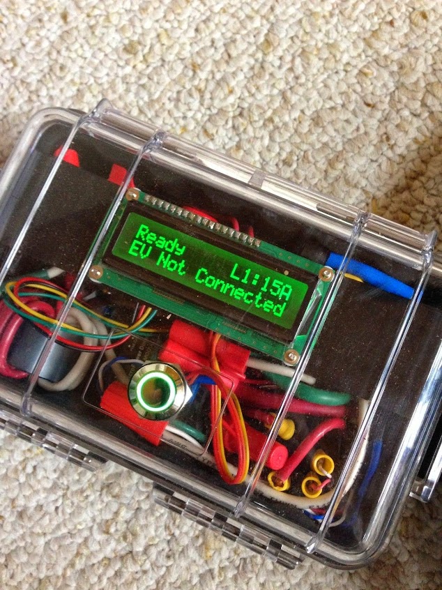
It looks like someone has bought OpenEVSE kits and put them together in a cheap box and is selling them as their own (BavarianMotorhaus) without acknowdging OpenEVSE. The price? a cool $1495.
Here is a photo:
OPENeve.JPG


You can see Chris' LCD and look carefully and you can see his board buried in there.

Here's the eBay Listing
 
eHelmholtz said:
Chris and friends,
It looks like someone has bought OpenEVSE kits and put them together in a cheap box and is selling them as their own (BavarianMotorhaus) without acknowdging OpenEVSE. The price? a cool $1495.
Here is a photo:
OPENeve.JPG


You can see Chris' LCD and look carefully and you can see his board buried in there.

Here's the eBay Listing

That's comical! I also like that L1 is set to 15 amps instead if 12 or 16. Someone that probably doesn't understand NEC and continuous loads. How could they possibly have a view of the EVSE market that they think they could sell any at this price.
 
Their ad also says "This is the EVSE that came with the Nissan Leaf." ???

When you go to their eBay store, they seem to be an auto dismantler - just lists a bunch of used parts. Kind of strange.
 
eHelmholtz said:
Chris and friends,
It looks like someone has bought OpenEVSE kits and put them together in a cheap box and is selling them as their own (BavarianMotorhaus) without acknowdging OpenEVSE. The price? a cool $1495.
Here is a photo:
OPENeve.JPG


You can see Chris' LCD and look carefully and you can see his board buried in there.

Here's the eBay Listing

Those crimps look positively horrible.

In designing and building Hydras I got a pretty good education in QD crimp terminals. Those look like the crappy Home Depot ones that smoke after charging a Volt for a month. :p
 
I got an Open EVSE (thanks Glenn) and have charged with it a couple of times.

One problem is the EVSE is still locked at the Leaf end after the charging is over. Didn't happen with Blink.

Anyone else seen this issue ?

(is this even an issue ... i.e. this is the expected behavior but somehow wasn't happening with Blink ?)
 
evnow said:
I got an Open EVSE (thanks Glenn) and have charged with it a couple of times.

One problem is the EVSE is still locked at the Leaf end after the charging is over. Didn't happen with Blink.

Anyone else seen this issue ?

(is this even an issue ... i.e. this is the expected behavior but somehow wasn't happening with Blink ?)

How is it locked? The EVSE doesn't control the mechanical release mechanism.
 
evnow said:
I got an Open EVSE (thanks Glenn) and have charged with it a couple of times.

One problem is the EVSE is still locked at the Leaf end after the charging is over. Didn't happen with Blink.

Anyone else seen this issue ?

(is this even an issue ... i.e. this is the expected behavior but somehow wasn't happening with Blink ?)

I am thinking the lock button got switched in the car so it now latches on.
 
MikeinDenver said:
I am thinking the lock button got switched in the car so it now latches on.

Hmmm ... let me check again. It just sounded strange to me that it started getting locked as soon as I switched to OpenEVSE. May be it is something my 2 year did ... pressing buttons at random while I was working in the garage to change from Blink to OpenEVSE.
 
I have encountered a feature on the power supply module that greatly concerns me.(MPM-04D-1205E)

I encountered a problem on the OpenEVSE I built for Evnow. I always considered 5V was 5V. Well maybe and not in the case of the MPM-04-1205SE.

All of the single voltage modules have no minimum load but the dual voltage unit is specified for minimum loads. For output 1 (12V) the min is 62ma. For output 2 (5V) the min is 30ma.

For our use the unit is essently unloaded except for the relay. As I understand the output 1 is regulated and the output 2 is somewhat regulated as a reflection. Sort of like the 12V on a computer supply.

To verify this I purchased 2 100 ohm power resistors at Fry's. I pulled my Diy Plus module from my EVSE for test.

With the module only with no display the 5V was 4.94V. With a 100 ohm resistor on the 12V line the 5V was 5.6V. Since this was already above the logic max of 5.25V I suspended my tests. I suspect with a 50 ohm load it would be above 6V. The biggest problem is that when the load is removed and the module goes from working hard to standby it generates a huge spike on the 5V.

The bottom line, for our use the 5V is junk! The only reason the OpenEVSE works is that cmos processors are very over voltage tolerant. The only reason I measured this is because the spike corrupted the eeprom on the processor of the unit I was building.

Unless you are using a very low power relay to drive a line powered relay it is likely your power relay pulls the 5V out of tolerance. As I recall the PB relay had a 80 ohm coil and the Qianji relay has a 55 ohm coil. On the next unit I build I will use an external regulator from the 12V line.


Anyone that I have built an EVSE for using a Plus board can have a free upgrade to a discrete regulator. Just show up at my doorstep or pay shipping both ways.

If you have a unit using a low power relay to power a 240V relay you do not need to be upgraded. This applies to the unit I just built and shipped and the unit for Evnow
 
GlennD said:
I have encountered a feature on the power supply module that greatly concerns me.(MPM-04D-1205E)

I encountered a problem on the OpenEVSE I built for Evnow. I always considered 5V was 5V. Well maybe and not in the case of the MPM-04-1205SE.

All of the single voltage modules have no minimum load but the dual voltage unit is specified for minimum loads. For output 1 (12V) the min is 62ma. For output 2 (5V) the min is 30ma.

For our use the unit is essently unloaded except for the relay. As I understand the output 1 is regulated and the output 2 is somewhat regulated as a reflection. Sort of like the 12V on a computer supply.

To verify this I purchased 2 100 ohm power resistors at Fry's. I pulled my Diy Plus module from my EVSE for test.

With the module only with no display the 5V was 4.94V. With a 100 ohm resistor on the 12V line the 5V was 5.6V. Since this was already above the logic max of 5.25V I suspended my tests. I suspect with a 50 ohm load it would be above 6V. The biggest problem is that when the load is removed and the module goes from working hard to standby it generates a huge spike on the 5V.

The bottom line, for our use the 5V is junk! The only reason the OpenEVSE works is that cmos processors are very over voltage tolerant. The only reason I measured this is because the spike corrupted the eeprom on the processor of the unit I was building.

Unless you are using a very low power relay to drive a line powered relay it is likely your power relay pulls the 5V out of tolerance. As I recall the PB relay had a 80 ohm coil and the Qianji relay has a 55 ohm coil. On the next unit I build I will use an external regulator from the 12V line.


Anyone that I have built an EVSE for using a Plus board can have a free upgrade to a discrete regulator. Just show up at my doorstep or pay shipping both ways.

If you have a unit using a low power relay to power a 240V relay you do not need to be upgraded. This applies to the unit I just built and shipped and the unit for Evnow


I think you are overreacting Glenn. There are over 1000 OpenEVSE units out there that use this supply that have been working flawlessly.

The OpenEVSE plus was never designed to switch large contactors. If using the reccomended relays and not pushing the 4w power supply to the absolute maximum with low quality chinese relays you have nothing to worry about.

I do have a new board coming in a couple weeks that will switch line voltage (240v AC coil) relays using an Opto-isolated chip. The current board will still be reccomended for 30a units and the new board for Non US (220v -240v) and Charge stations over 40a.
 
Glenn,

Perhaps you're being overly careful, but I like your level of caution.

I think you could get by with a 5.1V zener on the 5V output. Yes, that's brute force, but an easy retrofit. You may ask: isn't it wrong to put a zener on the output of a power supply? It would be for a low output impedance supply, but as Glenn mentions, this isn't a regulated output. In this case, the zener would just act like the minimum necessary load to get the voltage into tolerance. With 5.1V and 30mA, the zener will only consume 153mW maximum, and most likely much less.

You could also add a TI/National LP2954 5V Linear Regulator to the MPM-04-1205E 5V output. Doing that would require cutting a few board traces, so the average builder here wouldn't want to do this.

Note: Free LP2954 samples are available from TI at: http://www.ti.com/product/lp2954/samplebuy" onclick="window.open(this.href);return false;

Disclaimer: I work for TI. We lose money when you get free samples from us.

Bob


GlennD said:
I have encountered a feature on the power supply module that greatly concerns me.(MPM-04D-1205E)

I encountered a problem on the OpenEVSE I built for Evnow. I always considered 5V was 5V. Well maybe and not in the case of the MPM-04-1205SE.

All of the single voltage modules have no minimum load but the dual voltage unit is specified for minimum loads. For output 1 (12V) the min is 62ma. For output 2 (5V) the min is 30ma.

For our use the unit is essently unloaded except for the relay. As I understand the output 1 is regulated and the output 2 is somewhat regulated as a reflection. Sort of like the 12V on a computer supply.

To verify this I purchased 2 100 ohm power resistors at Fry's. I pulled my Diy Plus module from my EVSE for test.

With the module only with no display the 5V was 4.94V. With a 100 ohm resistor on the 12V line the 5V was 5.6V. Since this was already above the logic max of 5.25V I suspended my tests. I suspect with a 50 ohm load it would be above 6V. The biggest problem is that when the load is removed and the module goes from working hard to standby it generates a huge spike on the 5V.

The bottom line, for our use the 5V is junk! The only reason the OpenEVSE works is that cmos processors are very over voltage tolerant. The only reason I measured this is because the spike corrupted the eeprom on the processor of the unit I was building.

Unless you are using a very low power relay to drive a line powered relay it is likely your power relay pulls the 5V out of tolerance. As I recall the PB relay had a 80 ohm coil and the Qianji relay has a 55 ohm coil. On the next unit I build I will use an external regulator from the 12V line.


Anyone that I have built an EVSE for using a Plus board can have a free upgrade to a discrete regulator. Just show up at my doorstep or pay shipping both ways.

If you have a unit using a low power relay to power a 240V relay you do not need to be upgraded. This applies to the unit I just built and shipped and the unit for Evnow
 
GlennD said:
All of the single voltage modules have no minimum load but the dual voltage unit is specified for minimum loads. For output 1 (12V) the min is 62ma. For output 2 (5V) the min is 30ma.

For our use the unit is essently unloaded except for the relay. As I understand the output 1 is regulated and the output 2 is somewhat regulated as a reflection. Sort of like the 12V on a computer supply.

To verify this I purchased 2 100 ohm power resistors at Fry's. I pulled my Diy Plus module from my EVSE for test.

With the module only with no display the 5V was 4.94V. With a 100 ohm resistor on the 12V line the 5V was 5.6V. Since this was already above the logic max of 5.25V I suspended my tests. I suspect with a 50 ohm load it would be above 6V. The biggest problem is that when the load is removed and the module goes from working hard to standby it generates a huge spike on the 5V.

The bottom line, for our use the 5V is junk! The only reason the OpenEVSE works is that cmos processors are very over voltage tolerant. The only reason I measured this is because the spike corrupted the eeprom on the processor of the unit I was building.

Unless you are using a very low power relay to drive a line powered relay it is likely your power relay pulls the 5V out of tolerance. As I recall the PB relay had a 80 ohm coil and the Qianji relay has a 55 ohm coil. On the next unit I build I will use an external regulator from the 12V line.
This may account for some of the times my OpenEVSE has hung.
 
Back
Top