OpenEVSE - Open Source Charging Station

My Nissan Leaf Forum

Help Support My Nissan Leaf Forum:

This site may earn a commission from merchant affiliate links, including eBay, Amazon, and others.
I think we all have similar intentions :). Apart from the LCD & amp select button, I'd also like to add a button for start/stop. And maybe even (far future) a kWh counter...

Just received my usb programmer interface, and installed the arduino package. Now just waiting for the rest of the components to arrive.
 
Chris, are you planning on offering that power supply?
I googled the module you used, it's not availble from the usual sources (Digikey)

I guess the advtage of your DIY module is the ability to tell if the AC power source is 120V or 240V, which is a "nice to have" but I don't think it's absolutely needed for our DIY EVSEs

I think integrating the Open EVSE and the power supply on a single PCB would be good, but I guess it gets to be somewhat larger, of course then all that's needed is the CT and Relay (and fuses for good measure) to complete an EVSE
 
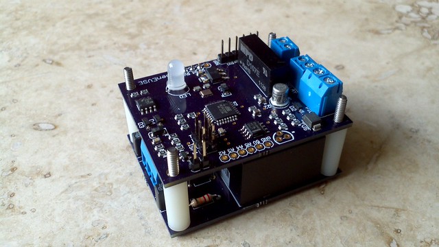
Here is the stack.


2012-02-16_08-53-54_262 by chris1howell, on Flickr

Mitch... I do plan to offer a power supply soon, first it will be just a basic supply. Later it will have more features. I have been working on a layout for a all in one board. I may release if I am happy with the combo design. I am also working on a Arduino shield.

I agree L1/L2 detection is a nice to have but that's not all that's going on. There are 2 chips that pass a very small current from each hot to ground past the relay. This allows the EVSE to do several self tests to ensure it is safe to operate. First with the relays open both chips should indicate no voltage present. If one of both have voltage the there is a problem with relay contacts stuck open. Then the EVSE can command relay closed. If neither chip indicates voltage ground is bad, 1 indicates a good ground and L1 and both with voltage indicates a good ground at L2.
 
Sounds good Chris (the stuck relay detection), however you're doing too good a design job, I doubt most of the commercially availble EVSE's fully implement the full J-1772 protocol and stuck relay detection :)

Thanks for your hard work,

Mitch
 
Mitch you are right most do not fully implement J1772. My goal is to design the best EVSE possible and provide the information free to the world. I hope this will improve the quality and price of the commercial options...I also hope to attract good people to help with the project. If EVSEs are better and cheaper hopefully there will be more places for ME to charge :lol:.
 
Chris:
So, what happens if the EVSE relay welds its points? I would think the charger would still shut down the charge function and the off-set J1772 pins would minimize sparking at the connecter. I have a switch on my EVSE to control the 240vac feed line and I make it a habit to make and to break the J1772 connection with the 240vac off. Comes from the experience of watching people blowing circuits.
Ladson
 
If the relay welds closed other than always hot leads in J1772 connector and the inability of gfci to kill the circuit if there is a ground fault. So you lose the two primary safety functions.

Ladson I would not worry about removing AC power, the pilot and proximity cicircuits are designed to do that for you. The EV charger will not start pulling significant current until commanded by the pilot and will stop pulling current with the proximity circuit.
 
chris1howell said:
If the relay welds closed other than always hot leads in J1772 connector and the inability of gfci to kill the circuit if there is a ground fault. So you lose the two primary safety functions.

If cost is not an issue, you could have 2 sets of relays setup in series, you do your testing for welded contacts after the 2nd set of relays, if opening that does't remove power from one or both hot legs, then you open the 1st relay and signal an error condition "relay contacts welded", and shut down until the EVSE is repaired. It takes an extra relay, and a second relay control output to do this, along with the proper testing logic.
 
Chris, beautiful design. I can't imagine which revision you'll be on by the time I get my EV.

How much current is the EVSE drawing when not in use?
I was thinking about gating the inputs of the power supply with triac so it's normally off. Then having a momentary contact switch that would bypass the gate. My idea is the EVSE would normally be in a non-energized state. Pressing the button would energize it. On initialization the EVSE would hold the gate closed to maintain it's power and start a timer waiting for work. If the timer expires, the gate is opened and circuit is de-energized. If the J1772 is connected, the circuit would remain energized. I'm sure the circuit only draws ~200ma but that adds up for the 12 hours a day it's not being used.

I was also thinking of having a two button design for my user input. A toggle button for menus and a select button to drill down. Pressing both buttons to back up. Once a parameter is selected the buttons would become up/down to alter it's value. I may get one just to play with the UI.

Thanks for some great work,

-Bill
 
Would it be possible to implement connectivity/control to a home monitoring system such as Vera or HomeSeer? One of the main issues I have with the LEAF is that I cannot remotely stop charging. However, if the EVSE could be remotely turned on and off then it might be possible to generate remote commands like "add 6 kWh of charge starting at 2 am".
 
chris...I see open evse gets better and better...cant wait to see what else you will dream up...the power supply with the same footprint as the evse board is so compact compared to the vinfinity from digikey...the arduino sounds promising too...kpc
 
mitch672 said:
chris1howell said:
If the relay welds closed other than always hot leads in J1772 connector and the inability of gfci to kill the circuit if there is a ground fault. So you lose the two primary safety functions.

If cost is not an issue, you could have 2 sets of relays setup in series, you do your testing for welded contacts after the 2nd set of relays, if opening that does't remove power from one or both hot legs, then you open the 1st relay and signal an error condition "relay contacts welded", and shut down until the EVSE is repaired. It takes an extra relay, and a second relay control output to do this, along with the proper testing logic.
This is how the Panasonic (Nissan) unit works. It does include stuck relay detection, and tests it every time before the pilot is asserted.

The only non-spec thing about it is the lack of diode detection (-12v). Panasonic has fixed this on their newer models.

-Phil
 
Ingineer said:
mitch672 said:
chris1howell said:
If the relay welds closed other than always hot leads in J1772 connector and the inability of gfci to kill the circuit if there is a ground fault. So you lose the two primary safety functions.

If cost is not an issue, you could have 2 sets of relays setup in series, you do your testing for welded contacts after the 2nd set of relays, if opening that does't remove power from one or both hot legs, then you open the 1st relay and signal an error condition "relay contacts welded", and shut down until the EVSE is repaired. It takes an extra relay, and a second relay control output to do this, along with the proper testing logic.
This is how the Panasonic (Nissan) unit works. It does include stuck relay detection, and tests it every time before the pilot is asserted.

The only non-spec thing about it is the lack of diode detection (-12v). Panasonic has fixed this on their newer models.

-Phil
(a bit OT, but relevant perhaps)
Phil - Is there a difference in PN or some other way to distinguish the old Panasonic from the new?

Thanks
 
essaunders said:
Ingineer said:
This is how the Panasonic (Nissan) unit works. It does include stuck relay detection, and tests it every time before the pilot is asserted.

The only non-spec thing about it is the lack of diode detection (-12v). Panasonic has fixed this on their newer models.

-Phil
(a bit OT, but relevant perhaps)
Phil - Is there a difference in PN or some other way to distinguish the old Panasonic from the new?

Thanks
All the units Nissan ships are of one basic design. The newer Panasonic models are being sold by other companies, such as Toyota. There have been no changes to the Nissan unit sold in the US, though Canadian units are slightly different.

-Phil
 
chris1howell said:
If the relay welds closed other than always hot leads in J1772 connector and the inability of gfci to kill the circuit if there is a ground fault. So you lose the two primary safety functions.

Ladson I would not worry about removing AC power, the pilot and proximity cicircuits are designed to do that for you. The EV charger will not start pulling significant current until commanded by the pilot and will stop pulling current with the proximity circuit.
Assuming that the proximity circuit works and the charger stops drawing current before the J1772 plug is removed (and the pilot signal disconnects), isn't there very little chance of the relays welding closed? Arcing only happens if there is current flowing when the relays opens.
 
DoxyLover said:
Assuming that the proximity circuit works and the charger stops drawing current before the J1772 plug is removed (and the pilot signal disconnects), isn't there very little chance of the relays welding closed? Arcing only happens if there is current flowing when the relays opens.
No, this could happen say if one of the semiconductors in the on-board charger were to fail. The resulting short circuit would result in high current and the opening of the relays under this condition could result in a weld. This would be a safety issue, which is why it's a good idea.

-Phil
 
I just wanted to say thanks to Chris for posting all of the information for testing EVSEs, and showing how easy it really is to test an EVSE, for all states. Here is the post, if you have not seen it yet:

http://code.google.com/p/open-evse/wiki/EVSE_TESTING" onclick="window.open(this.href);return false;
 
Back
Top