chris1howell
Well-known member
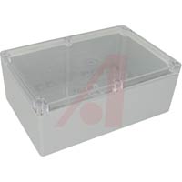
z0ner said:Can I haz enclosure?
Does he have one in "throwback" clear plexiglass?")
Yes, I will post purchase info as soon as I get it.
No clear, just metal for now...


z0ner said:Can I haz enclosure?
Does he have one in "throwback" clear plexiglass?


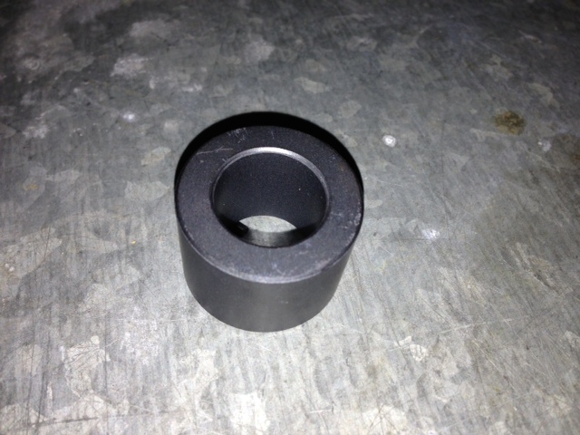
The best place to mount the tubular ferrite inductors are where the power enters and exits the EVSE enclosure.waidy said:Dear Open EVSE enthusiasts: our Open EVSEs are *almost* done. The electrician should be coming next week to do the install. We have one part left from the kit. Would you advise where this part go? It it too big for my figure

waidy said:Dear Open EVSE enthusiasts: our Open EVSEs are *almost* done. The electrician should be coming next week to do the install. We have one part left from the kit. Would you advise where this part go? It it too big for my figure
Great. thanks. I will leave it for my electrician.Barbouri said:The best place to mount the tubular ferrite inductors are where the power enters and exits the EVSE enclosure.waidy said:Dear Open EVSE enthusiasts: our Open EVSEs are *almost* done. The electrician should be coming next week to do the install. We have one part left from the kit. Would you advise where this part go? It it too big for my figure
Below is a photo of a commercial Leviton Evr-Green 160 EVSE showing the placement in its enclosure.
If you only have one inductor place it on the AC power in.
Greg C.
Thank you. I will connect our 75Amp OpenEVSE directly to the 100Amp breaker.MashedPotato said:OpenEVSE includes GFCI functionality and should be installed on a non-GFCI circuit.
waidy said:Our two 75Amp OpenEVSEs are complete. Darren connects one of the EVSE via a 120V cable plugged directly to a 120V 12Amp outlet. He scrolled the display (via a push button) and everything looked as expected. He then plugged in the J-connector to the Rav4EV. Display sequence was: Vehicle connected, EVSE ERROR NO GROUND. Please advise what we have done wrong.
OK. I will have to wait for my electrician to come for install. I will report. Thank you.TonyWilliams said:waidy said:Our two 75Amp OpenEVSEs are complete. Darren connects one of the EVSE via a 120V cable plugged directly to a 120V 12Amp outlet. He scrolled the display (via a push button) and everything looked as expected. He then plugged in the J-connector to the Rav4EV. Display sequence was: Vehicle connected, EVSE ERROR NO GROUND. Please advise what we have done wrong.
Could you try it again at 240 volts?
I see. Thanks for the detail explanation and instruction on how to test via 120V 3 wires. Our 120V connection is indeed a 3-wires cable in which the ground wire was connected to the ground bar. We didn't do the re-config on the 75 Amp relays. This explains our failure.garygid said:if the big relay in your 75 amp EVSE only operates on 240v, not 120v, you should disconnect one leg of the "little relay to the big relay", and not expect the big relay to operate, and not try to connect to a vehicle.
Then, the 120v test should pass the Ground test only if the 120v AC connection is 3 wires, including a round wire to a properly grounded 3-prong receptacle in the wall.
Yes, when I tested with 120v at the workshop, I used a 2-wire AC connection, but I had to use the menu to disable the Ground Check in order to demonstrate the EV Simulator features and test the OpenEVSE Control pilot as it would be affected by a typical EV.
I looked. It is there.garygid said:The ground fault might be due to a missing ground wire between the OpenEVSE controller board and the ground strip. It should be a wire right next to the Control Pilot connection.
I know all my outlets are grounded at the breaker box. Half of my garage outlets has GFCIs and half don't. We tried with two different non-GFCI outlets and get the "EVSE ERROR NO GROUND" massage on both cases.garygid said:The re-config of the 75 amp relay is only suggested to protect the relay's coil windings and contacts which might not operate properly at 120v. See the voltage ratings on your relay coil to determine if it is OK to apply 120v to the relay coil.
Or, the 120v receptacle that you used was not properly grounded?
Yes. Darren put the test leads in. Thanks you so much for the thoughtful advise.chris1howell said:Hi Waidy... It should work fine when you plug into 240V. The test leads should be on the output of the big contactor. 120V is not enough to close the contacts, so if the contacts are open the test will fail. At 240V the contactor will close and the tests should pass...
Enter your email address to join: