Adding a Brusa charger under the hood for '11/'12s

My Nissan Leaf Forum

Help Support My Nissan Leaf Forum:

This site may earn a commission from merchant affiliate links, including eBay, Amazon, and others.
davewill said:
KillaWhat said:
A though, having not looked under here myself yet.
Is it out of the question to remove the metal support bracket, and do something like industrial foam tape (Industrial Velcro?) the board to the potted electronics area?
Couldn't you mount it using standoffs to the bottom of your new plate? That should be nice and solid while avoiding touching the rest of the components. Quite reversible, too.

I believe the thinking with this was that once mounted to the bottom of the new plate, it might be really difficult to reach under there and connect it back up.
Not much in the way of "spare" wire on those connections.
 
It should be possible to use the high current lugs for the HV connection, but given that the additional charger pushes less than 10 amps DC, perhaps it is feasible to tie into the much small screw terminals for the ceramic (bleed?) resistor. That way you don't have to touch the critical 250 Amp connection at all. I didn't think to explore this possibility when I had the cover open, so only one of these smaller terminals is pictured, but I think the other is essentially the same. This approach is potentially less of a headache, especially for those who might be considering reversing the mod to avoid hassles when taking the car in for warranty service, etc.

Howdy
 
Lots of discussion on the physical aspect of this. What about the CAN communication? I see that as the larger challenge.

I haven't broken out the manual yet to look, but does the inverter create the DC and then there is a separate charger that then meters out the charge current? In my world of standard Level 1 and Level 2 AC charging, this functionality is all integrated in one charger unit (AC in and regulated DC out, controlled via CAN).
 
marcucci said:
Lots of discussion on the physical aspect of this. What about the CAN communication? I see that as the larger challenge.

I'm hoping that as the mechanics of this get further along, we will have to address the software side.

That's not my forte, but I was kind of hoping that this thing can be rigged as a slave.
Hook it up parallel and let the leaf control the charge?

Anyway, you Can buss guys be thinking about this :roll:

My cables came today.
Somebody owes me a Pizza.
The Output wiring is not more than 12gauge, in fact I think it's more like 14.
It even came with the needed gland.

I am always reluctant to do something that cannot be undone, and to that end I want to make a little "T" adapter cable that goes between the J1772 leader, and the harness to the charger. I dug into there some today, and It looks pretty simple. Unplug the leader, plug the adapter in between, and it can be removed in minutes.

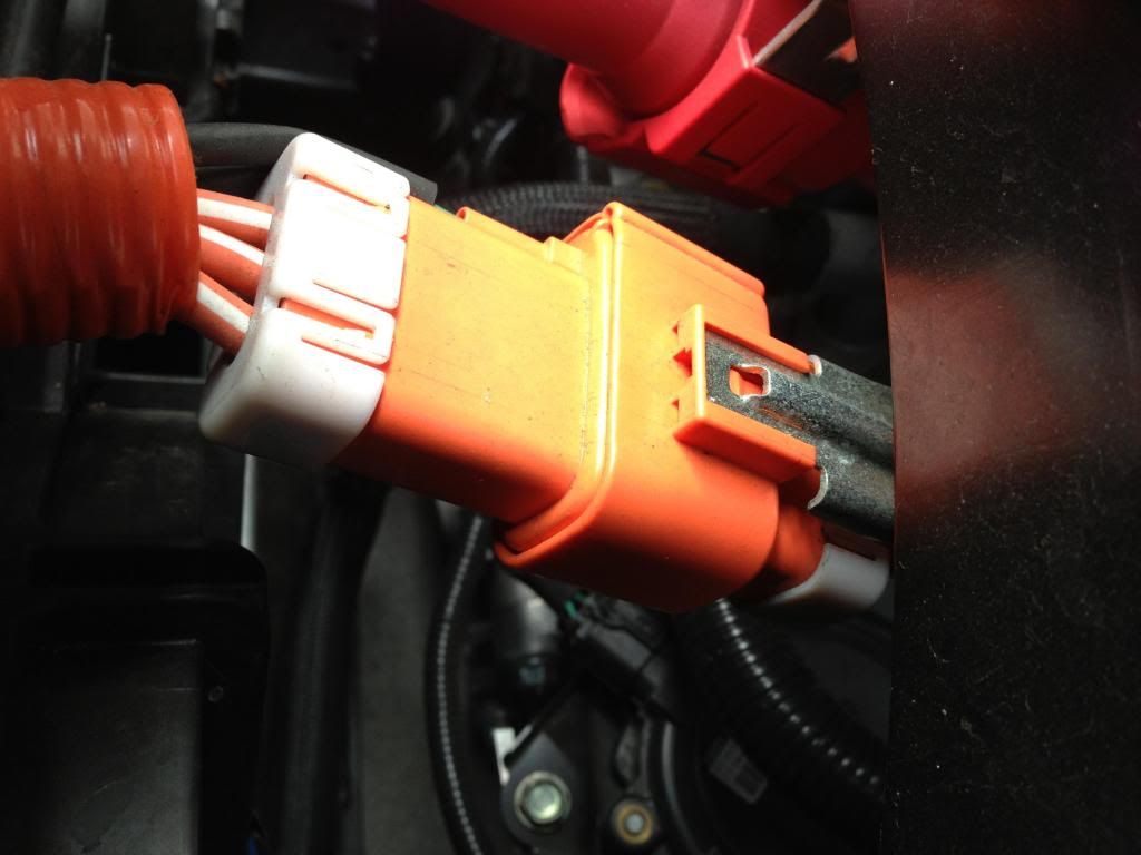
This is the plugset set we need, with all the pins/sockets.
Contains the 2 AC hots, a chassis "Ground" and the 2 small gauge pilot signal wires. (one of which may also be a chassis ground?)

Can anybody figure out how to order it?

 
marcucci said:
I am always reluctant to do something that cannot be undone, and to that end I want to make a little "T" adapter cable that goes between the J1772 leader, and the harness to the charger. I dug into there some today, and It looks pretty simple. Unplug the leader, plug the adapter in between, and it can be removed in minutes.

This is the plugset set we need, with all the pins/sockets.
Contains the 2 AC hots, a chassis "Ground" and the 2 small gauge pilot signal wires. (one of which may also be a chassis ground?)

As I said earlier in this thread this piece of the puzzle is the one I am most excited about for my own personal interests. I feel the exact same way. I want to mount an OpenEVSE on a cord reel under the hood and this is the major roadblock to doing that well.

I couldn't find any markings on this which would indicate a part number or manufacturer. I tried using the Nissan connector numbers in the wiring diagram but couldn't find anything. I tried browsing through the major connector manufacturers catalogs but didn't come across anything :( I've tried offerring to buy the connectors from the totaled LEAFs. So far no luck at all. Hopefully you guys have better luck! Let me know if I can help, buy a sample connector, etc.
 
QueenBee said:
I tried browsing through the major connector manufacturers catalogs but didn't come across anything :( I've tried offerring to buy the connectors from the totaled LEAFs. So far no luck at all. Hopefully you guys have better luck! Let me know if I can help, buy a sample connector, etc.
I'm sure a $430 solution isn't what you are looking for, but the J inlet side of this connector pair is available as part of the factory replacement charging port assembly for the aforementioned steep price. Unfortunately, the other half might be part of the even more pricey ($1200) "engine room" wiring harness, so there is clearly a motivation to find the connector by itself. Too bad the salvage parts from crashed LEAFs didn't work out, that seems like a better option. Unless they want to keep the cars as intact as possbile to rebuild them, you might have an easier time offering to buy the complete charge port assembly from the salvage car, rather than asking them to cut off the connector (maybe for about half of the above replacement part price?). You could cut it apart yourself and sell the J inlet on Ebay for ~$100. That gets you the connector you want for the onboard OpenEVSE reel for for about $100. Still not cheap, hopefully better alternatives will emerge.

Howdy
 
hgoudey said:
Unless they want to keep the cars as intact as possbile to rebuild them, you might have an easier time offering to buy the complete charge port assembly from the salvage car, rather than asking them to cut off the connector (maybe for about half of the above replacement part price?). You could cut it apart yourself and sell the J inlet on Ebay for ~$100. That gets you the connector you want for the onboard OpenEVSE reel for for about $100. Still not cheap, hopefully better alternatives will emerge.

Yeah, that was the angle I was going for. I think there goal was to rebuild them :(
 
There are some used parts available according to this post from imwoody36
http://www.mynissanleaf.com/viewtopic.php?f=37&t=10713&start=10" onclick="window.open(this.href);return false;
 
I will speculate a bit.
The charger takes the AC and turns it into (perhaps noisy) DC,
suitable to charge the battery pack. The only question is how
how much current to deliver. There are 4 constraints:

1. The max DC current that the charger itself is allowed
to produce, according to its design parameters.
Call this Max-DC, a "fixed" design parameter of the charger.

2. The max AC current that the charger itself is allowed to draw
from the external power source, according to its design parameters.
Call this Max-AC, again a "fixed" design parameter of the charger.

3. The Max (AC) Amps that the EVSE says that the charger should
draw from the external power source. This is Max-Amps derived
from the Control Pilot signal from the EVSE.

4. The maximum DC current that the BMS will allow to be
delivered to the battery pack, which depends primarily upon the
battery temperature, and the state of charge of the cells.
Call it Max-Charging.

Presumably the BMS sends the Max-Charging (amps and tenths)
value over the EV-CAN bus to the charger. I am guessing that the
BMS only limits the charging current during the last part of the
charging, the taper-down part. I suspect that this value is also
used to taper off the QC charging.

So, faced with 2 design constraints, and two input limitations,
the charger does tend best that it can do at any given moment.

The EV-CAN bus also has the current going into the battery pack,
but apparently the charger does not use that to limit its own
current production, or this piggy-back additional current would
not work.

Such is my simple-minded conjecture.
 
KillaWhat said:
My cables came today.
Somebody owes me a Pizza.
The Output wiring is not more than 12gauge, in fact I think it's more like 14.
It even came with the needed gland.

I am always reluctant to do something that cannot be undone, and to that end I want to make a little "T" adapter cable that goes between the J1772 leader, and the harness to the charger. I dug into there some today, and It looks pretty simple. Unplug the leader, plug the adapter in between, and it can be removed in minutes.

This is the plugset set we need, with all the pins/sockets.
Contains the 2 AC hots, a chassis "Ground" and the 2 small gauge pilot signal wires. (one of which may also be a chassis ground?)

Can anybody figure out how to order it?
My semi-premade cables and data connector came in yesterday. I had figured they wouldn't be a heavy gauge though. Mine look to be 12 gauge.

As for the AC connector- if we can't find the part to make our own harnesses, the second best thing to do would be to modify the existing J1772-Yazaki harness, and if and when you sell the car, replace this part with a new $400 one. But by that time hopefully it will be cheaper, and used parts avalible. I mean, I'd rather make a T too, but... :roll: At least the part looks to be easily removed from the leaf to do the splicing. The two small wires are pilot and proximity (for the switch on the handle to instantly cut the current before removal).

As far as CAN, and getting the max current value, I'm trying to get can-do up and running on my laptop to study Gary's charging log but I'm getting a funky error of "Run-time error '53' File not found." This is after installing the VBA support via the puzzle solve program. Will have to read through the can-do thread and tinker some more with it today.
 
OK.
As I watch my Brusa approaching on FedEx tracking, I'm feeling the pressure here.
Allow me summarize my (our?) goals at this point;

1) Installation should be transparent.
Plug in a 6.6 Kw capable EVSE, and the thing just does its job.
I would like it to be set up so that the Leaf's charging system controls everything, and the Brusa is a parallel slave. Plug in the J1772, the car negotiates the connection, it signals the EVSE to close the contact "Beep...... Beep Beep Clunk" and we are charging.

Now the Brusa sees that it is "OK TO CHARGE" because we have hijacked a signal somewhere that tells it so. (Maybe just the 240AC going hot to the Brusa would do it?)

As the Pack approaches 100%, maybe the Brusa stops charging at 95%, and we let the OBC take it the rest of the way. Or, if we have a timer set, at 80% the leaf tells the EVSE to stop charging, and we lose the 240VAC (and the Brusa loses the "ok to charge signal also) Easy Peasey.

2) "Quickly" removable. I'd like to be able to pull this thing out in an hour and leaving it so that they would have to call CSI Fukashima to find any trace. I don't want to have THAT conversation with Nissan where they patiently explain why my Right rear wheel bearing has failed because of my Warranty voiding charger install.
I think we agree that except for some tweaking we have the high voltage connection issue solved, and its 100% reversible. Mounting plate is reversible. Tank relocation should be reversible as well.

Option a) If we could find that intermediate socket/ plug set I think that would solve the reversible input connection 100%. And you KNOW that the guys in Xing Chow or wherever sell the things for like $1. if we could find them.

Option b) If we could get the J1772 Inlet and leader assembly at a reasonable price, we could "have our way with it in weird and unnatural ways", and just swap out the original if we needed to. Looks like a 10 minute job.

the second best thing to do would be to modify the existing J1772-Yazaki harness, and if and when you sell the car, replace this part with a new $400 one. But by that time hopefully it will be cheaper, and used parts avalible. I mean, I'd rather make a T too, but... :roll: At least the part looks to be easily removed from the leaf to do the splicing. The two small wires are pilot and proximity (for the switch on the handle to instantly cut the current before removal).

Option c) Not my favorite option, but at this point..... OK.
The J1772 Inlet and leader assembly uses a HUGE orange split convoluted tube as a "cover". If we locate a generic plug / socket combo, inline, small diameter (3/8") that can easily handle the current, I can remove the assembly, Install those connectors onto the pair of 240VAC input legs, and pop them out through the slit in the convoluted tubing. To reverse it, I just unplug my harness from those 2 inline sockets, and slide them back into the orange tubing out of sight.

CSI is gonna smell a rat, but otherwise it's going to remain hidden. This supposes that the Brusa is operating as a slave, and all we need from this harness is the 240VAC and not the pilot signal (although if we had to, we could do something similar with those as well)

Now for option X.
I understand this is not what we want. Just hear me out.
My plug set came with that nice J1772 Inlet already wired on.
I have a Blink EVSE, and I have an EVSE Upgrade 16 AMP.
TEMPORARILY, while we try to solve a couple problems, I/we could open the hood, and connect the EVSE #1 to the Brusa Inlet, and plug in EVSE #2 to the Leaf Inlet... then let them each do their thing independently.............. I know, but just mull it over for a while.
We might gain some insight while we try to solve the reversible plug set problem, and I'm now charging at 6.6 Kw, and It's not like it took extra work.

Anybody have the Brusa Programming Software?
 
Update:

Option c) Not my favorite option, but at this point..... OK.
The J1772 Inlet and leader assembly uses a HUGE orange split convoluted tube as a "cover". If we locate a generic plug / socket combo, inline, small diameter (3/8") that can easily handle the current, I can remove the assembly, Install those connectors onto the pair of 240VAC input legs, and pop them out through the slit in the convoluted tubing. To reverse it, I just unplug my harness from those 2 inline sockets, and slide them back into the orange tubing out of sight.

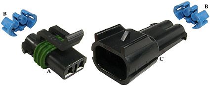
So, I went ahead and ordered an assortment of watertight automotive type connectors capable of 19 amps continuous with contacts for 12AWG wire, in single, double and triple configurations (thinking we might want to carry the chassis ground from the J1772 as well)

I'll see how big they are, whether they will fit under the orange tubing in any configuration other than single in line / staggered and get back to you with pictures and part numbers / source if we like them.
NOT expensive.

I'm thinking the whole thing, once connected, can be put back under the Orange tubing, and the "New" Brusa harness will emerge from the tubing at the Interconnect plug/socket and make for a very clean install.


KevinSharpe said:
KillaWhat said:
Anybody have the Brusa Programming Software?
You could try asking EVTV... they've done a lot of work with the Brusa in the past :)


The guys that quickly determined that regen was not beneficial and then retracted? :roll: Not sure I would rely on their advice. I think there is plenty of great advice here already and I'm impressed with some of the ideas and general comments so far.
 
EVDRIVER said:
The guys that quickly determined that regen was not beneficial and then retracted? :roll: Not sure I would rely on their advice.
Given they are actively supporting open hardware development I don't see any conflict of interest here... if they've worked with the Brusa chargers and are prepared to share their knowledge then why not?
 
KevinSharpe said:
EVDRIVER said:
The guys that quickly determined that regen was not beneficial and then retracted? :roll: Not sure I would rely on their advice.
Given they are actively supporting open hardware development I don't see any conflict of interest here... if they've worked with the Brusa chargers and are prepared to share their knowledge then why not?

Conflict of interest? Just saying I would not take EV design tips form them based on their track record. Far more skilled and talented people in this thread for sure.
 
EVDRIVER said:
Far more skilled and talented people in this thread for sure.
Lots of skilled people here and working on the open projects that EVTV is sponsoring.... seems silly to reinvent the wheel given the original question;

KillaWhat said:
Anybody have the Brusa Programming Software?
 
KevinSharpe said:
EVDRIVER said:
Far more skilled and talented people in this thread for sure.
Lots of skilled people here and working on the open projects that EVTV is sponsoring.... seems silly to reinvent the wheel given the original question;

KillaWhat said:
Anybody have the Brusa Programming Software?

Brusa software can be downloaded online for free.
 
EVDRIVER said:
Brusa software can be downloaded online for free.

Sure can, it's on the EV Motork Verks site, although I heard it is a bit clunky. I've heard that the best way is to go ino hyper-term first and establish connection there (it has a nice ASCII menu with the current status and readings) THEN pull up charge star. I have a laptop with a dedicated serial port running Win XP that should work nicely with the project.

Unfortunatly I will be traveling next week and won't be able to play with the charger. I have CAN-do running on my netbook now, just trying to learn the ins and outs of t and plot some values.
 
Back
Top