RegGuheert
Well-known member
Now that we have the capacity to read all cell-pair voltages, I think it would be good to start looking at the performance of our packs to try to determine if there are consistent trends between cars as to which cell(s) lose capacity fastest and which cell(s) lose capacity slowest. This information will be useful in determining if module rotation is warranted and, if so, it should also aid in determining which rotation patterns might be best.
For reference, page EVB-20 of the November 2010 Edition, April 2011 Revision of the Nissan LEAF Model ZE0 Series service manual contains a pictorial view of the layout of the 48 battery modules in the 2011/2012 LEAF. Each module contains two pairs of cells, so there are a total of 96 cell voltages which are measured and reported by the LEAF. The service manual numbers the modules from MD1 to MD48 and the cell voltages from Cell-1 to Cell-96. Cell-1 is at the highest-voltage end of the stack with its positive terminal connected to the positive terminal of the battery. Cell-96 is at the lowest-voltage end of the stack with its negative terminal connected to the negative terminal of the battery. To determine which cells are contained in a given module, simply multiply the module number by two for the higher cell number and subtract one from that product for the lower cell number. For example, module MD23 contains the following two cell voltages: Cell-45 and Cell-46.
Modules MD1 through MD24 are contained in a stack under the rear seat with MD1 on the far passenger's side and MD24 on the far driver's side. Modules MD25 through MD28 are located under the rear driver's side footwell. Modules MD29 through MD36 are located under the front driver's seat. Modules MD37 through MD44 are located under the front passenger's seat. Modules MD45 through MD48 are located under the rear passenger's side footwell.
The exact location of each module can be seen in the MODULE LAYOUT diagram from page EVB-20 of the service manual, shown below:

In order to determine the relative capacity of the cells in your LEAF, please follow these steps:
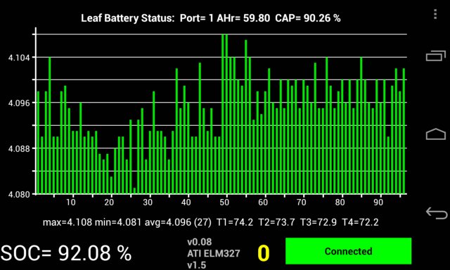
1) You must first achieve a high degree of cell balancing, which is occurs at the top of the charge range. So you will need to perform at least one 100% charge to balance your pack. Sometimes, you will need to charge to 100% several days in a row to achieve a good balance. I find that charging to 100% using 120V gives the best amount of cell balancing. You can also let your LEAF sit, plugged in, following a 100% charge for a few hours to let it attempt to rebalance once the pack fully cools.
2) Once your pack is fully balanced, measure and record your cell voltages using the one of the methods shown in the second post of the this thread, which I will reserve and update as new techniques for reading cell voltages are developed. This is your record of how well balanced you pack is.
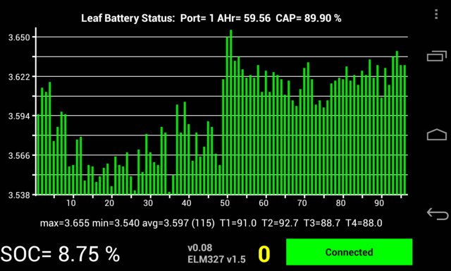
3) Now, discharge the battery pack to a point where the lowest cell voltage is 3712 mV or lower. This voltage is from Nissan's CELL VOLTAGE LOSS INSPECTION procedure found on page EVB-65 of the service manual. In order to do this, Nissan recommends putting the vehicle in READY and setting the following:
- A/C set temperature: Full hot
- A/C fan speed: Maximum speed
- A/C air outlet: Defroster
- Headlamp: High beam ON
- Door glass: Full open
Monitor the available charge gauge and watch for it to go down to two bars or less. This should take about four hours if the battery was fully charged. It may take less time if your pack is degraded.
4) Once your pack is at or below 2 charge bars, measure and record your cell voltages. Ensure that the lowest voltage recorded is 3712 mV or lower. If it is above this voltage, repeat step 3) above. This is your record of how much voltage difference there is between all of the cells in your LEAF at a low SOC. If you pack was very well balanced in step 2) above, then the cells with the highest voltages here should have the LEAST capacity degradation and the cells with the lowest voltages should have the MOST capacity degradation. (Note: this test does NOT tell how MUCH capacity degradation your battery pack has, only how much difference there is between different cells in the pack.)
Once you have performed the test, please post images of your results from both step 2) and step 4) here (preferred) or simply type in the top six and bottom six voltages from both steps along with their cell-pair numbers. I will collect the data, perhaps in a Google spreadsheet, and will try to find capacity loss trends by plotting histograms of results which we achieve.
Please post if you find any errors in the test procedure or would like to point out new ways we can measure cell-pair voltages. I can then update either this post or the second one. Thanks in advance!
For reference, page EVB-20 of the November 2010 Edition, April 2011 Revision of the Nissan LEAF Model ZE0 Series service manual contains a pictorial view of the layout of the 48 battery modules in the 2011/2012 LEAF. Each module contains two pairs of cells, so there are a total of 96 cell voltages which are measured and reported by the LEAF. The service manual numbers the modules from MD1 to MD48 and the cell voltages from Cell-1 to Cell-96. Cell-1 is at the highest-voltage end of the stack with its positive terminal connected to the positive terminal of the battery. Cell-96 is at the lowest-voltage end of the stack with its negative terminal connected to the negative terminal of the battery. To determine which cells are contained in a given module, simply multiply the module number by two for the higher cell number and subtract one from that product for the lower cell number. For example, module MD23 contains the following two cell voltages: Cell-45 and Cell-46.
Modules MD1 through MD24 are contained in a stack under the rear seat with MD1 on the far passenger's side and MD24 on the far driver's side. Modules MD25 through MD28 are located under the rear driver's side footwell. Modules MD29 through MD36 are located under the front driver's seat. Modules MD37 through MD44 are located under the front passenger's seat. Modules MD45 through MD48 are located under the rear passenger's side footwell.
The exact location of each module can be seen in the MODULE LAYOUT diagram from page EVB-20 of the service manual, shown below:
In order to determine the relative capacity of the cells in your LEAF, please follow these steps:
1) You must first achieve a high degree of cell balancing, which is occurs at the top of the charge range. So you will need to perform at least one 100% charge to balance your pack. Sometimes, you will need to charge to 100% several days in a row to achieve a good balance. I find that charging to 100% using 120V gives the best amount of cell balancing. You can also let your LEAF sit, plugged in, following a 100% charge for a few hours to let it attempt to rebalance once the pack fully cools.
2) Once your pack is fully balanced, measure and record your cell voltages using the one of the methods shown in the second post of the this thread, which I will reserve and update as new techniques for reading cell voltages are developed. This is your record of how well balanced you pack is.
3) Now, discharge the battery pack to a point where the lowest cell voltage is 3712 mV or lower. This voltage is from Nissan's CELL VOLTAGE LOSS INSPECTION procedure found on page EVB-65 of the service manual. In order to do this, Nissan recommends putting the vehicle in READY and setting the following:
- A/C set temperature: Full hot
- A/C fan speed: Maximum speed
- A/C air outlet: Defroster
- Headlamp: High beam ON
- Door glass: Full open
Monitor the available charge gauge and watch for it to go down to two bars or less. This should take about four hours if the battery was fully charged. It may take less time if your pack is degraded.
4) Once your pack is at or below 2 charge bars, measure and record your cell voltages. Ensure that the lowest voltage recorded is 3712 mV or lower. If it is above this voltage, repeat step 3) above. This is your record of how much voltage difference there is between all of the cells in your LEAF at a low SOC. If you pack was very well balanced in step 2) above, then the cells with the highest voltages here should have the LEAST capacity degradation and the cells with the lowest voltages should have the MOST capacity degradation. (Note: this test does NOT tell how MUCH capacity degradation your battery pack has, only how much difference there is between different cells in the pack.)
Once you have performed the test, please post images of your results from both step 2) and step 4) here (preferred) or simply type in the top six and bottom six voltages from both steps along with their cell-pair numbers. I will collect the data, perhaps in a Google spreadsheet, and will try to find capacity loss trends by plotting histograms of results which we achieve.
Please post if you find any errors in the test procedure or would like to point out new ways we can measure cell-pair voltages. I can then update either this post or the second one. Thanks in advance!
")