Control Circuit Board Mounting Under the New Brusa Mounting Plate, cont.
OK; Spent the weekend working on the Brusa mount and that circuit board bracket.
First the disclaimer, then the good news (for me), and then the discouraging news, and lastly the results of my weekend’s work.
Disclaimer:
DO NOT DO THIS !!!. High voltage… you will die!!
Seriously, if you don’t know what this is….Don ‘t do it!
HV Disconnect
 The Good News:
 I pulled the battery negative, then pulled the High Voltage disconnect (easily, since I had a set of Tony’s RED thumbscrews under there). Pulled the Inverter housing, then disconnected and pulled the circuit board bracket. I’ve done this so many times now I think I have it down to about 18 Minutes.
AND….When I was all done, and put I it all back together….. The car was still ALIVE!!!!
(I Confess, I was a bit concerned considering what I had put that circuit board through.)
The Discouraging News: The short version, then we will get into the meat of this.
Again, it’s all about the under-the-plate clearance issue. We are trying to stick a circuit board under there that is 19 to 20 mm tall, in a space with only 17 to 18 mm clearance. Period!
As in “If you just dropped the circuit board right on top of the inverter, it would still extend higher than the plane of our plate.
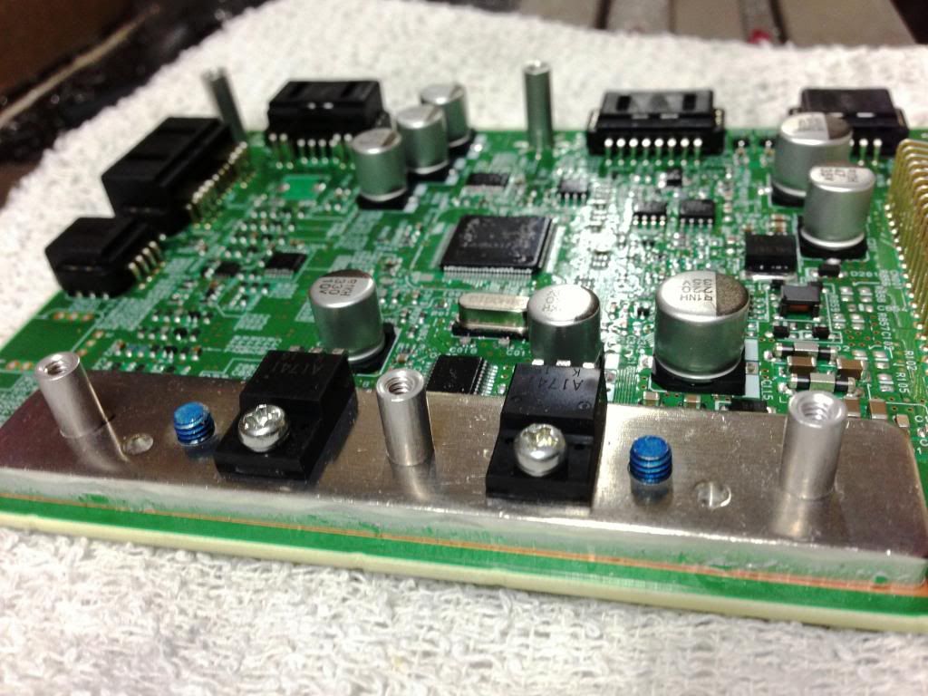
There is (on my car at least) a “lip” around the potted section of the inverter guts. Like they put a plastic “bowl” in there, put the electronics in, poured the potting compound in, and the “lip” of the bowl extends higher than the compound. That lip catches a section of the board, and that’s what is keeping it from sitting flush.
After spending a BUNCH of time farting with this, I evaluate our options as:
1) Increase Bottom clearance: Mill down the section of the lip that is causing the problem. OK, but Even if you pulled it out of the car, mounted it on a mill, and did a perfect, precise reduction in height, there is no way to hide it if Nissan has to pull it apart for a warranty repair. I think it would work, but that’s’ not the way I’m going to go.
2) Increase Top clearance: Mill out the plate.
Option " A". Completely mill out a hole through the new inverter cover plate, giving you 3/16” increased clearance. Then make a “Mounting Plate” for the Bottom of the Brusa that will cover the hole, and give us the ability to attach the Brusa from the bottom as it was intended, then attach the top plate from above.
Option “B” . Make your plate out of ¼” Plate. Flat mill it down to about <1/8” giving the resulting >1/8” increase in clearance. This will work.
Note that if you do either of these options, you have to provide enough space for the PLUG end of the White connector not to be encroached upon. If you had the right equipment, and were starting from scratch, Using a 1/4” plate this might be the way to go. I’m not, because I already have the plate made, and ……. I don’t want to.
Option “C”: Increase the height of the plate with a thicker gasket. Unfortunately, This is the option I am going to have to pursue. I am going to go back to my bracket assembly, reduce everything to absolute minimums, check the clearance one more time, then get a solid number on how much clearance I need to gain, then decide on a gasket thickness. I’m thinking 5/32”.
My plan is I’m going to find out how much replacement gaskets cost, and if it’s not absurd, I’ll micrometer one, figure out how many I need, and stack them till its tall enough. Ugly, but if you look at how they are made, this WILL work!
I’m REALLY not looking forward to cutting a 3/16” gasket out of a material that is tough enough not to compress significantly..
So if stacking gaskets is going to cost more than about $100, I’m going to use a 5/32 extruded sheet of HDPE plastic, hopefully UV stabilized, and mill a gasket out of it. Easier than cutting a thick rubber gasket, unless anybody knows someone in that business with a CAD water jet.
Here is what was done this weekend:
First step;
I cut out the basic traced shape of the bracket, located and drilled the 4 mounting holes and the 6 standoff holes. Inverted the plate on top of the circuit board, and measured the height of the standoffs I need to make to make the top of the plate perfectly flush with the top of the white plug.
MY tall ones are 11.5 mm
And short ones are always 5mm shorter, in this case 6.5 mm.
I used 4 X 40 SAE threaded round standoffs and 4 X 40 X ¼” flat head screws for all the tops, and 4 X 40 X 3/8” for the 3 that require a longer screw on the bottom. I think you could use #6 hardware and it would fit fine.
Here are the Standoffs in place
 Here is the Completed Bracket. It’s not perfect, but it works.
You need to make enough relief so that you can attach and disconnect all the plugs. The cosmetic holes are just that; vanity. The plate can be a lot simpler and still work fine.
Here is the assembled bracket and circuit board sandwich.
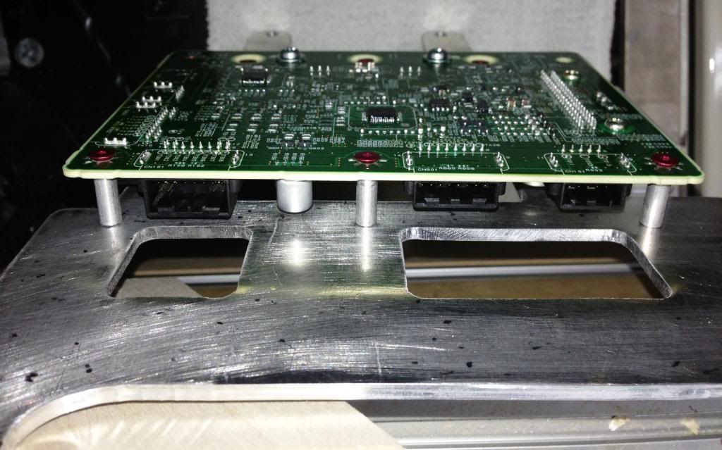
The clearance on the bottom of my bracket will be adjusted by adding ½” OD ¼” ID aluminum spacers UNDER the where the bracket mounts to the inverter housing. I’m really paranoid about dropping something in the inverter, so when I get the correct height for these spacers, I’ll weld them onto the bottom of the bracket so they stay. I’ll use countersunk flat head M5/0.8 screws to attach the bracket.
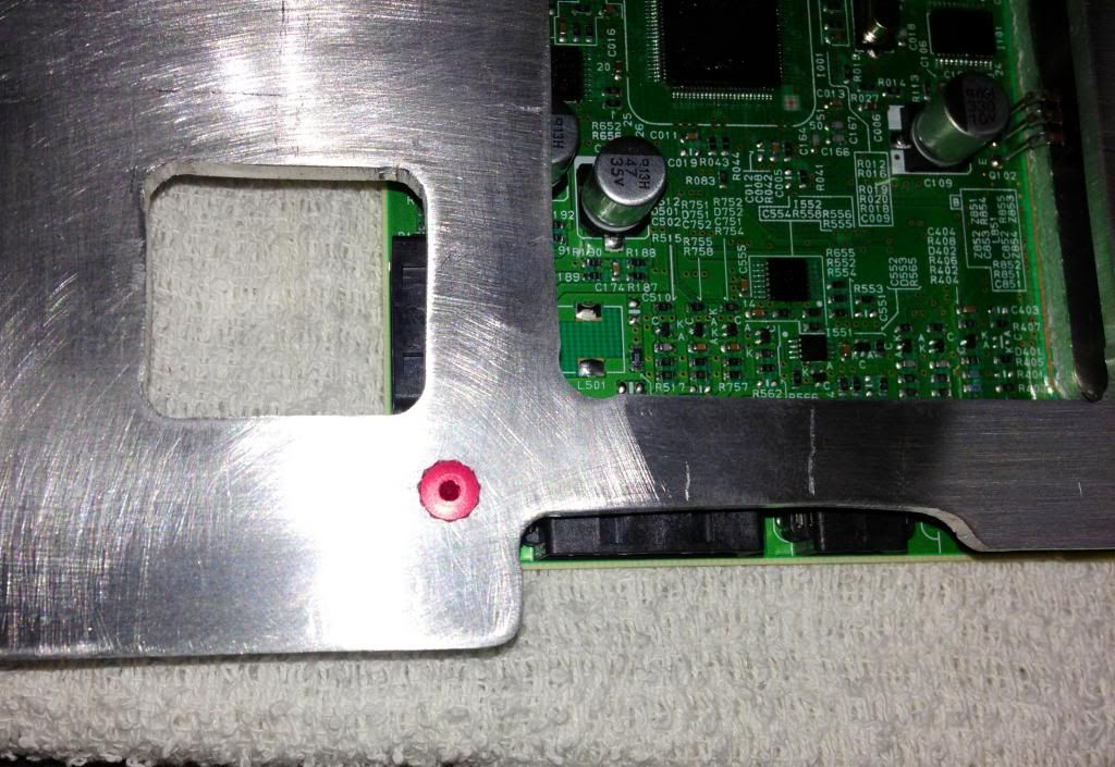
Close-up of Bracket. Flat head screws used everywhere so as not to add any height.
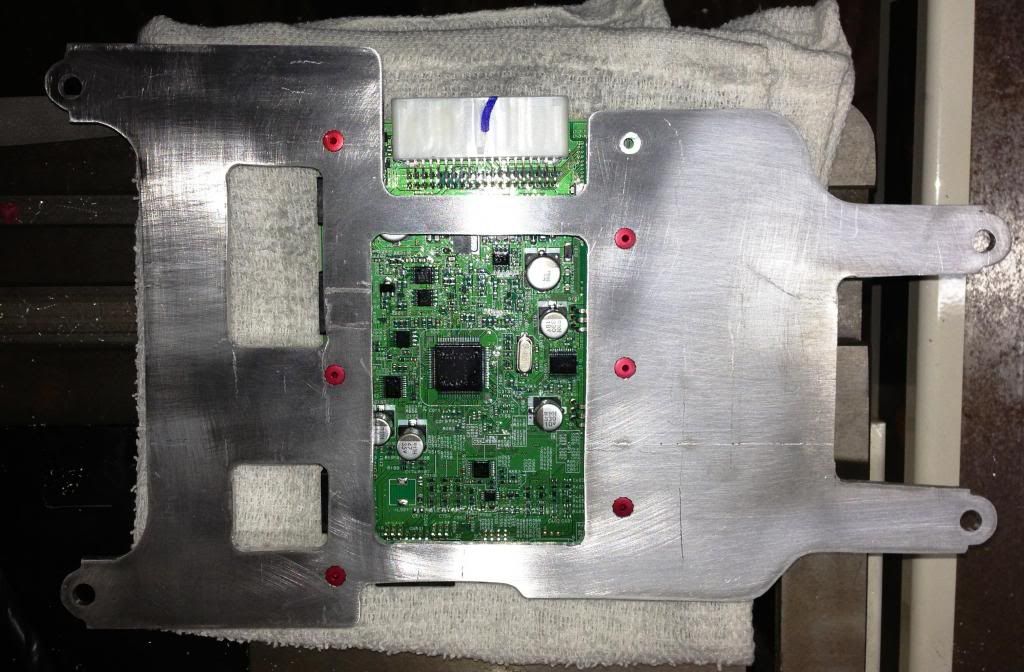
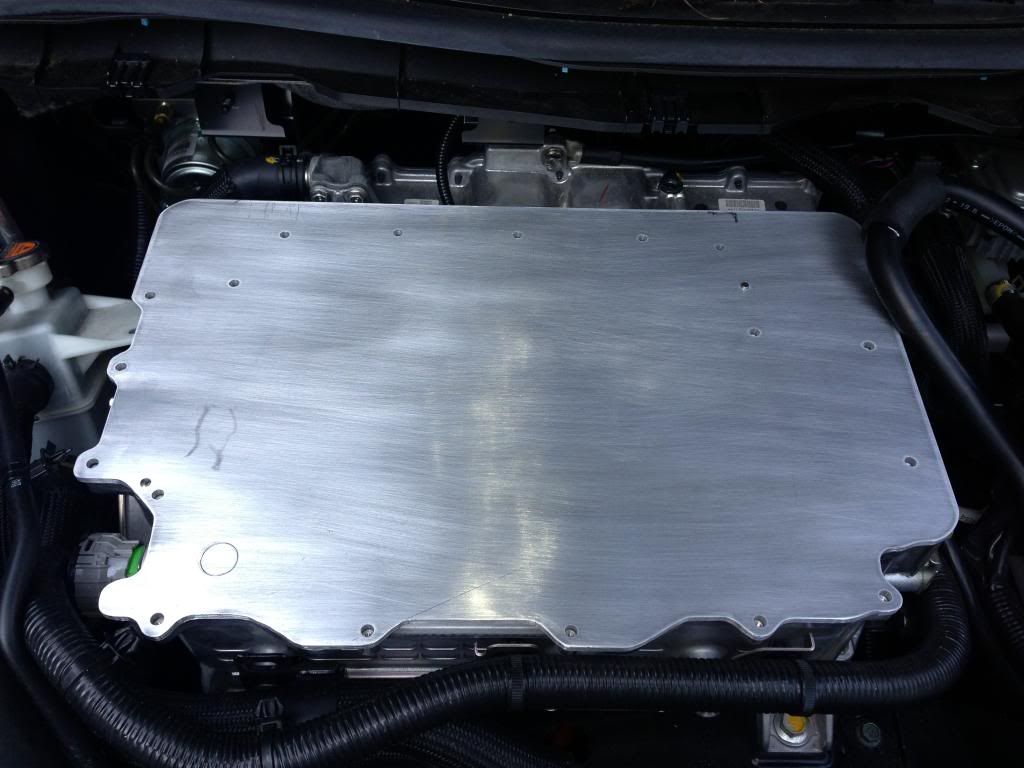
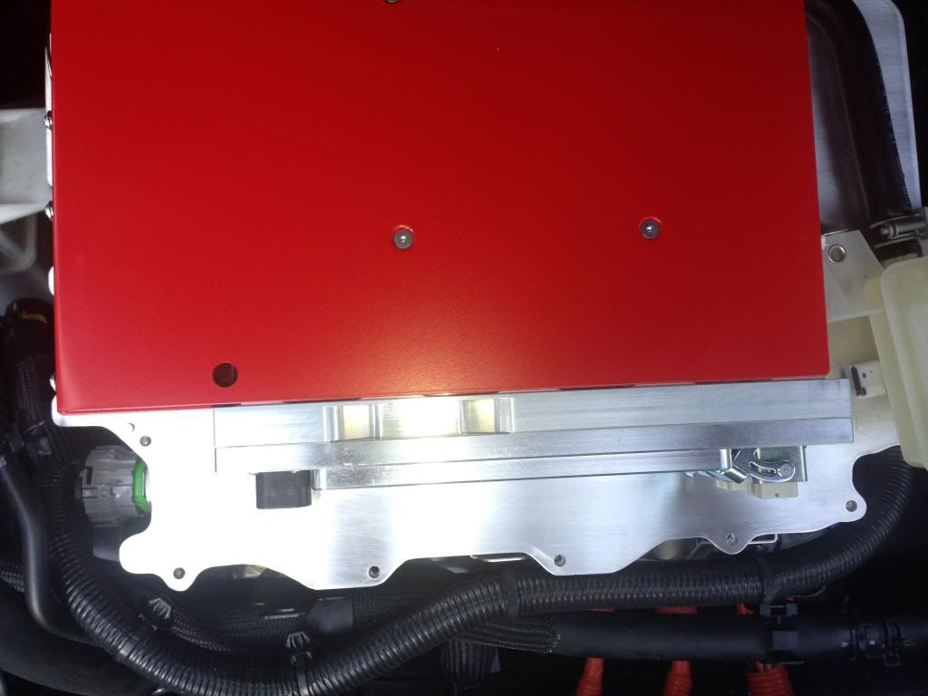
 First Time my Plate was put in Place so I can locate the charger exactly
Some of you know that I started with a 12" X 18" X 3/16 Plate, only to discover that I might not have enough room on the drivers side to relocate the Brake Fluid Tank. Do yourself a favor and start with a width of 19.5". (It's not so much the tank bracket width, as the wire coming out the side hitting the Brusa.
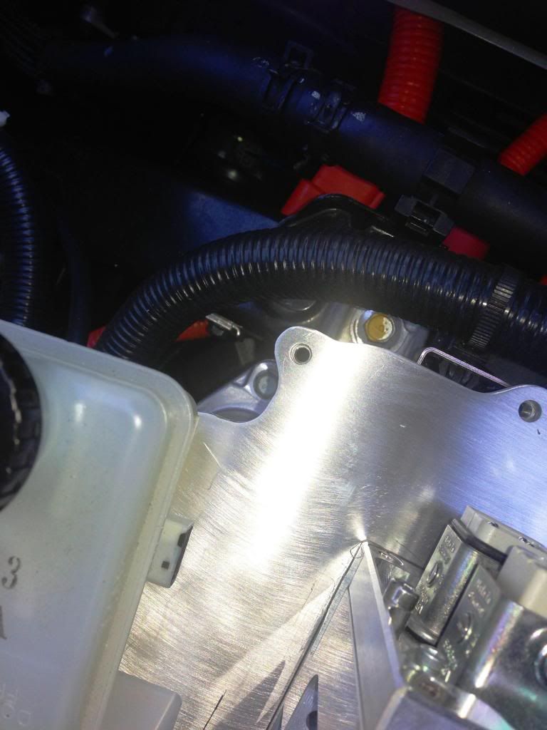
 This is a Close-up of the Plate showing Alignment
 This is the Charger in place Overview. This is how it will look completed.
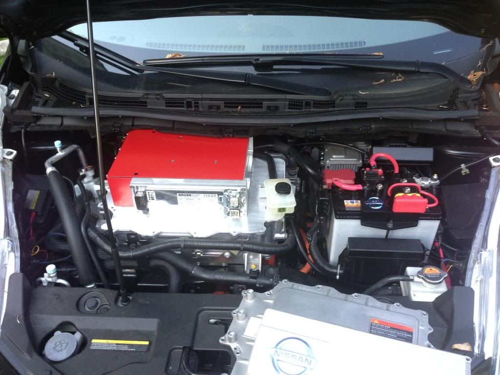 This is My Correct Charger Placement
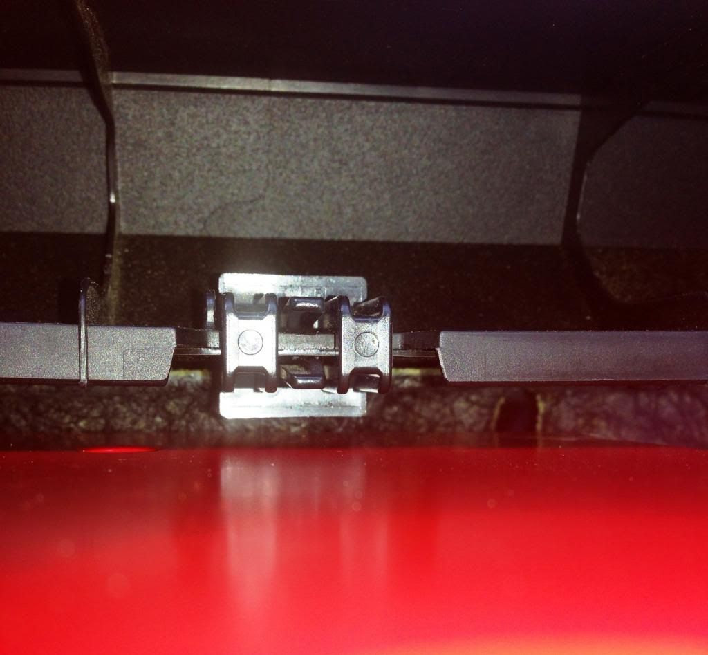
 Note on TOP clearance:
 I mounted my plate on the top of the housing, with the gasket, and then placed the Brusa in position. I was able to slide a 1/8” shim under the black lip at the rear of the assembly without a problem. I was able to slide a 3/16” Shim under, but it WILL TOUCH that 1 clip that hangs down always.
And remember, you need to reduce the height of your tank and bracket mounting standoffs (on the main plate) by the amount of height you add to the plate or they won’t match up on the side.
Charger in place showing the Rear Clearance
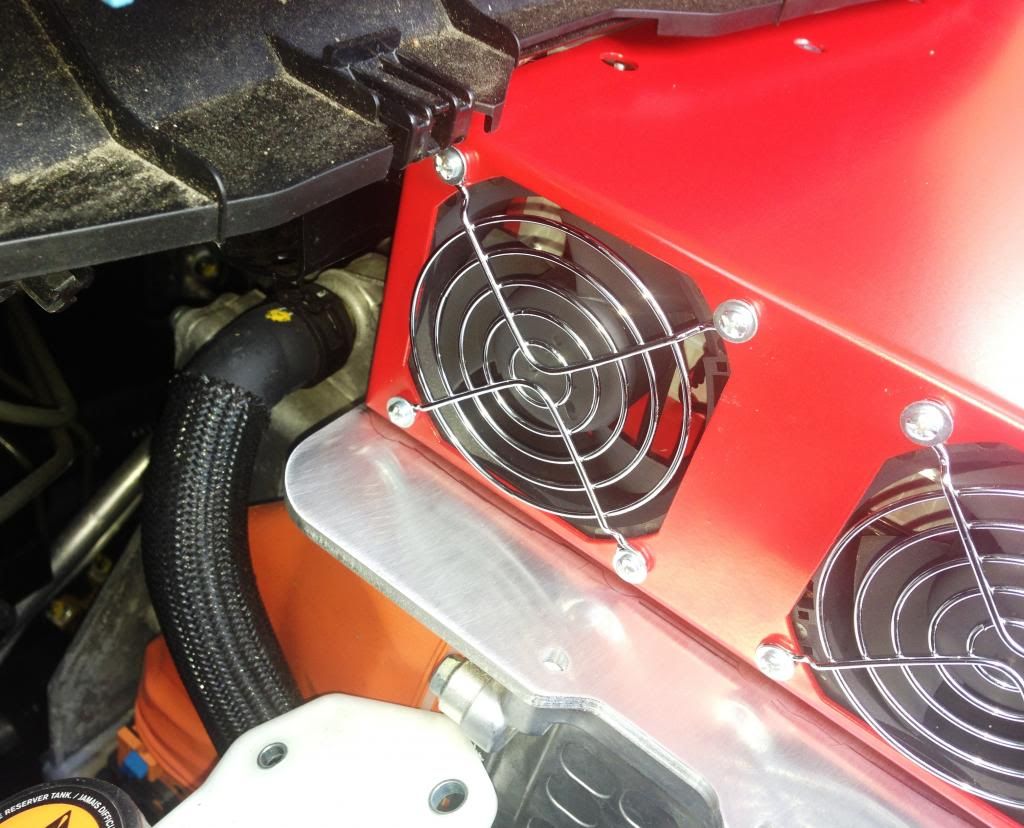 Close-up of the Top Clearance showing that clip that is the lowest point.
So. I am going to shave my standoffs until they are at minimums, Solve my height extending gasket problem, mount it all up and install it. Going to tap the J1772 as soon as I’m ready to leave the plate mounted.
Looking forward to you “operations” guys solving the programming problems, and where we get our +12VDC and tap the can BUSS.


")