Hi all,
After much futzing around trying to understand the problem, I removed the horn relay for testing, and found the the coil pins were shorted out.
And the output leg was open relative to the other two legs.
Anyway, most importantly, I finally realized that the wimpy horn sound was the
original ANTI-THEFT HORN (actual location unknown).
It turns out that the pressing on the steering wheel must have been designed to activate
both the ANTI-THEFT HORN and the normal HORN.
Then I checked the 10A fuse for my normal HORN, and it was blown! And the 10A fuse for the ANTI-THEFT horn was fine.
(should have been the first thing to check, but I was lazy to get the fuse tool from the the fuse compartment at left end of dash board, and also I did not suspect the fuse, because I thought my horns were making *some* sound.)
I now have a new relay which has incompatible legs, I might solder things together to get things working.
I'm now looking for a wiring diagram that explains how the 3-legged horn relay is connected.
UPDATE:
I'm looking at this diagram ( http://www.mynissanleaf.com/wiki/images/e/e3/Nissan_LEAF_Power_Supply_Routing_Circuit.gif" onclick="window.open(this.href);return false; ), not sure if I understand it...
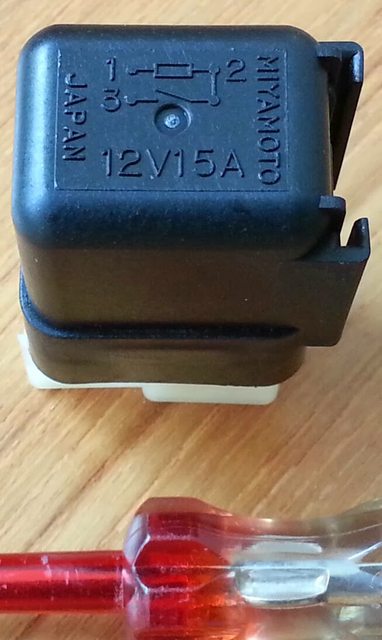
It seems to show that the + line goes thru the 10A horn fuse, then to pin 2 of the HORN RELAY.
Pin 2 of the relay is the common pin as shown here:
I suppose pin 3 is connected to chassis ground and the pin 1 goes to one terminal of the horn, and the other terminal of the horn goes to ground (the longer connector).
If this is the circuit, then I don't understand the purpose of the horn relay, it does not serve to reduce the current load on the steering wheel momentary switch contacts.
Am I right?


")