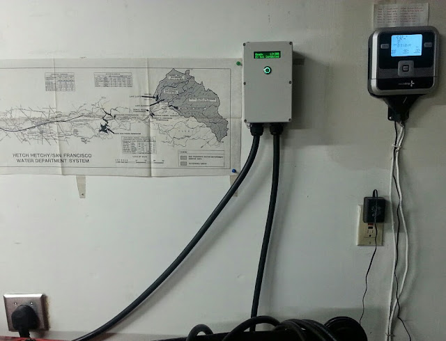
I ordered Chris' charge station combo and got it completed the day I received it. It's up and running and appears to function exactly as it should. Like everything I build myself, I'm always a little nervous until the device proves itself, so can you critique my build and see if anything stands out as suboptimal?
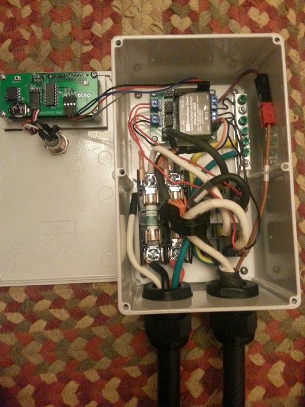
I used all the parts from the kit, however the 32A "heavy duty" Dostar J1772 I bought from the store had wiring too thick to slip inside the supplied wiring connectors. On the connections from the J1772 cord to the relays, I removed the plastic wiring connector housings, opened up the slotted part where the wire would normally crimp, then I soldered and shrink-wrapped those connections. Any problems there?
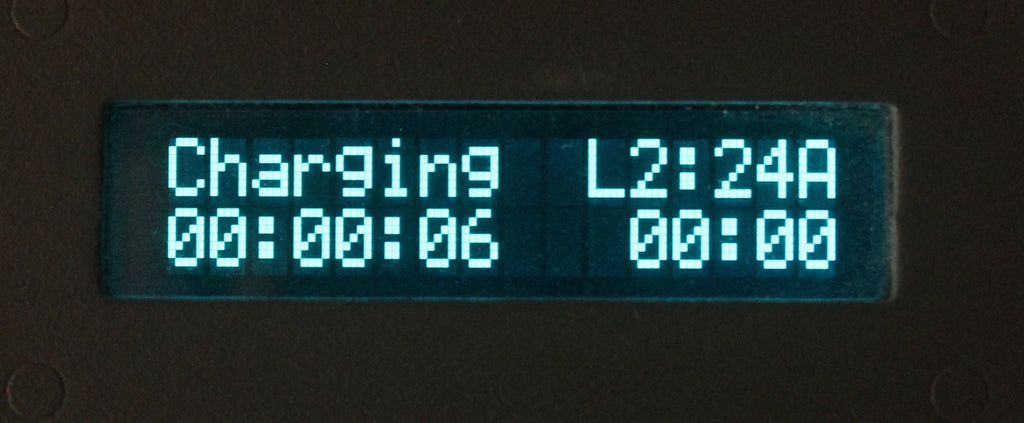
Also, all the pics I've seen on the web have the charge current set to 24 amps. Mine jumps from 20 amps to 25 amps...was there a software or hardware change that was recently made? I have it set to 25 amps, is that safe given the above build? I am using a 40 amp range cord and a 32A Dostar J1772. The outlet is a NEMA 14-50 with 6/3 wire on a 30 amp breaker. Car is a 2013 with the 6.6kw charger.
Thanks.