Announcing the J1772 Hydra

My Nissan Leaf Forum

Help Support My Nissan Leaf Forum:

This site may earn a commission from merchant affiliate links, including eBay, Amazon, and others.
nsayer said:
You're right about the 48A combined limit, but there's no particular reason you can't achieve the 48A per vehicle as well, as long as you get contactors and J1772 cables and plugs that are up to it.

The NEC says that for a 60A circuit you're going to need to run AWG 4 copper wire. If you don't have that in place already, that'll be a necessary prerequisite. You'll need to run that all the way into the bus module inside the Hydra (that's no problem, though. A Cooper-Bussman 16220-2 is what I specify, and it can go all the way to AWG 4 on the load side and 2/0 on the line side). On the line side, I believe AWG 8 would be enough to go from the bus module to the contactors, and then the other side of the contactors would be attached directly to your J1772 cables.

Getting 50A rated contactors is the next step, and if they don't have a 12VDC coil, then you'll need pilot relays to drive them.
I have the 60A line coming to a subpanel in the garage, and the 20 and 40 are split from that panel (20 goes up and over, 40 goes 2ft to the AV EVSE-RS). I'd only have to replace the 2ft of wire coming from the subpanel - no problem there. This was all permitted and installed in 2011 for EVSE use only, so I'm not worried about supply side at all.

If it's easy enough to source the 48/50A parts for each head then that makes sense. I assume then that the 48A limit is imposed in software and since there'd be a 48A limit on the input side of the hydra then that would be the failsafe should the controller fail and attempt to feed two cars at max amperage.

I'm not an electrical engineer, but I pretty much understand everything said, so am trying to determine what I need to brush up on before attempting a project like this. Any particular suggestions?
 
Devin said:
I have the 60A line coming to a subpanel in the garage, and the 20 and 40 are split from that panel (20 goes up and over, 40 goes 2ft to the AV EVSE-RS). I'd only have to replace the 2ft of wire coming from the subpanel - no problem there. This was all permitted and installed in 2011 for EVSE use only, so I'm not worried about supply side at all.

If it's easy enough to source the 48/50A parts for each head then that makes sense. I assume then that the 48A limit is imposed in software and since there'd be a 48A limit on the input side of the hydra then that would be the failsafe should the controller fail and attempt to feed two cars at max amperage.

I'm not an electrical engineer, but I pretty much understand everything said, so am trying to determine what I need to brush up on before attempting a project like this. Any particular suggestions?

There's no particular "failsafe" to prevent the Hydra from offering excessive power to the vehicles, but it would take a spectacular firmware error for it to happen, and the result would be that the circuit breaker behind the Hydra would pop (so that's the failsafe, really). The firmware mods for this variant of the Hydra haven't yet been written, but there will be a UI to set the maximum input current. Again, if you "fib," all that's going to happen is that the breaker will pop.

If you purchase an assembled Hydra board, then the entire skill set required is simple mechanical fabrication and basic wiring.

The most important thing when constructing the high-current path is to insure the crimps or screw connections are absolutely secure and correct. A resistance of a tenth of an ohm at 30A at 240V is 90 watts of power loss, most of which will turn into heat.
 
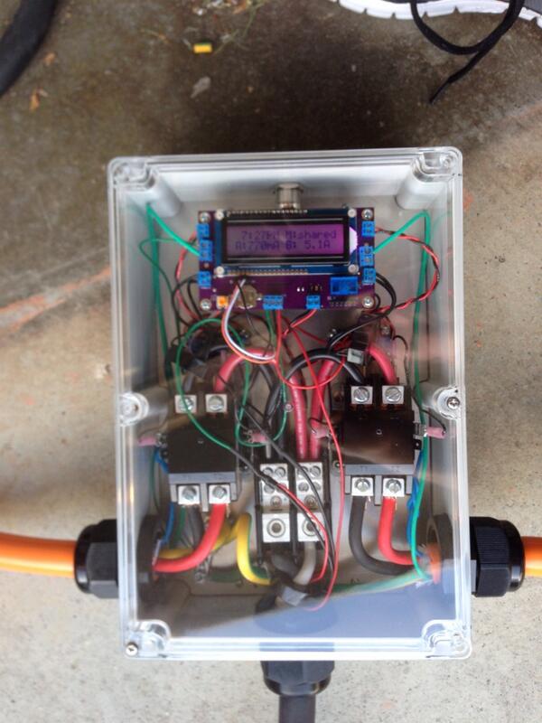
The EVSE variant of the Hydra is now available in the store. I've built two prototypes - the reference 16/30 design, and what I call the "mega-hydra" - with 50A rated contactors and cables/plugs for a 25/50 capable design.

I have designed and use an opto-isolated triac "contactor adapter" board to allow the 12v relay outputs on the Hydra logic board to drive line powered contactors.

The firmware defines 4 timer events that can pause and unpause the system differentiated by day-of-week, and the clock can even automatically correct for DST.

The limiting factor was the contactors I found. There's no reason in principle that you couldn't buy heftier ones and make a Hydra capable of full power by simply swapping them out and upsizing the internal wiring one notch.

BoXzOKpCMAALqzY.jpg
 
Nice work! Hopefully one day I'll be a two EV household and will need to build one of these!

Is the pilot wire really green on that J1772 cable?
 
QueenBee said:
Is the pilot wire really green on that J1772 cable?

Yeah. Odd choice if you ask me. Which they didn't, of course. :)

There's also a blue wire, but it's not actually hooked up to proximity like you'd expect. I've used the 30A version of that cable for a "splitter" style Hydra and had to get into the handle and connect it (the splitter Hydra transmits inlet proximity transitions to the plugs to insure you can't yank the inlet plug under load).
 
nsayer said:
QueenBee said:
Is the pilot wire really green on that J1772 cable?

Yeah. Odd choice if you ask me. Which they didn't, of course. :)

There's also a blue wire, but it's not actually hooked up to proximity like you'd expect. I've used the 30A version of that cable for a "splitter" style Hydra and had to get into the handle and connect it (the splitter Hydra transmits inlet proximity transitions to the plugs to insure you can't yank the inlet plug under load).

Must have been extra green wire laying around the factory. Is that the J1772 cordset that is sold for the JuiceBox, I think that's the only place I've seen the orange cables used. I'm guessing that wouldn't pass UL certification.
 
QueenBee said:
Must have been extra green wire laying around the factory. Is that the J1772 cordset that is sold for the JuiceBox, I think that's the only place I've seen the orange cables used.

Yes. It's their 60A cable.

I'm guessing that wouldn't pass UL certification.

Why not? All of the components that touch 240VAC are themselves UL listed (with the one exception being the contractor adapter, but I don't have a whole lot of doubts that that part would hold the process back), and all of them are operating within their specifications. If I had the money lying around to buy a Tesla I could spend it instead on getting the Hydra UL Approved and then I would feel much better about actually selling assembled ones.

I actually feel somewhat better about the Mega-Hydra than I do about the reference design. The reference design uses 30A relays with QD terminals, and run at 30A it does get warm (that said, a reference design unit has been in daily hard service for months now with no signs of damage). I haven't tested the Mega beyond 30A (I don't have a beefier car), but at 30A it shows absolutely no signs of any warmth anywhere. I don't actually know if the #10 .25" QD terminals are UL approved when carrying that much current. With Mega, it's not an issue because the entire high-current path is screw terminals.

If anything, I think the limiting factor for productizing the Hydra (beyond the limited market) would be passing FCC Part 15 muster rather than the safety aspects. After all, it's what amounts to a giant 16+ MHz square wave generator in a plastic box. Not the textbook way of limiting EMI.
 
nsayer said:
QueenBee said:
Must have been extra green wire laying around the factory. Is that the J1772 cordset that is sold for the JuiceBox, I think that's the only place I've seen the orange cables used.

Yes. It's their 60A cable.

I'm guessing that wouldn't pass UL certification.

Why not? All of the components that touch 240VAC are themselves UL listed (with the one exception being the contractor adapter, but I don't have a whole lot of doubts that that part would hold the process back), and all of them are operating within their specifications. If I had the money lying around to buy a Tesla I could spend it instead on getting the Hydra UL Approved and then I would feel much better about actually selling assembled ones.

I meant just the cord set itself. I'd expect that UL would require green wires to be only used for grounding just as the NEC does.

I really like that all your high amperage connections are in nice lugs. One of the weaknesses of my OpenEVSE IMO is the quick disconnects.

It'd be nice if UL was more open as it would be neat to improve the designs to include any modifications that would be needed to pass UL testing.

Ah, hadn't even thought of interference issues. I guess another reason to get the new metal box that Chris has now.
 
QueenBee said:
I meant just the cord set itself. I'd expect that UL would require green wires to be only used for grounding just as the NEC does.

I'm guessing that since UL approval in this instance is an encompassment of the completed unit and that there would be no user-servicible parts inside that they would actually not care about the wire colors. And the NEC does allow you to use whatever color wire you like provided that you "disambiguate" any "wrong" wire colors by wrapping some electrical tape of the correct color near the termination (this according to an electrician friend of mine whose work regularly passes inspections).

I really like that all your high amperage connections are in nice lugs. One of the weaknesses of my OpenEVSE IMO is the quick disconnects.

You don't find QDs on contactors rated above 30A, and given the temperature rise I see in the reference design Hydras I build I rather suspect that they're not really supposed to go above 24A continuous. If you read between the lines, the reference OpenEVSE design - since it comes with 30A fuses - is really only rated for 24A charging.

It'd be nice if UL was more open as it would be neat to improve the designs to include any modifications that would be needed to pass UL testing.

That's what bugs me a bit about UL... Look at the name: "underwriters' laboratories." Their purpose is to make the world a better place for insurance companies. What it really amounts to is an insurance company tax on consumer products, because if you look at the fine print of your homeowner's (or renter's) insurance policy, you'll likely find that if a fire is caused by a non-UL-approved device (or by un-permitted electrical work), you are likely not covered. And that tax is substantial. I actually requested a quote from them for an inspection of the Hydra. They said that for a "preliminary" engineering consultation - basically them looking at a prototype and giving me a list of things I need to fix if I want it approved - that they would charge me $10,000. I would imagine that actual certification would be even more. Not only that, but certification is not a one-time event. My understanding is that they check up on you periodically to make sure you have not made any modifications to the design that would impact their certification. I can't imagine that is free.

Ah, hadn't even thought of interference issues. I guess another reason to get the new metal box that Chris has now.

Yeah. For what the Hydra is - a homemade device controlling thousands of watts of power - I value the ability to see inside while it's operating. You definitely want to be able to see whatever evidence may be available if it starts to smoke. I won't lie - a couple of the early prototypes had heating problems. But lessons were learned and the current reference design - with the proper (expensive) crimp QD terminals - I believe is safe.

But as a product - with that coveted UL approval - there'd be no need for such visibility. A NEMA-4 grounded metal box with just a window for the LCD would, no doubt, take care of any RFI.

By the way, that's the one issue with Chris' enclosure - it's not actually grounded. The mounting plate to which all of the components are attached is plastic - so there's no path from the ground bus to the chassis. He really should add a braid from the ground bus to one of the screws that attaches that plate to the frame. Otherwise if, say, an input hot line comes loose and makes contact with the chassis, it's a shock hazard - and the GFI built-in to OpenEVSE won't be of any help.
 
nsayer said:
QueenBee said:
I meant just the cord set itself. I'd expect that UL would require green wires to be only used for grounding just as the NEC does.

I'm guessing that since UL approval in this instance is an encompassment of the completed unit and that there would be no user-servicible parts inside that they would actually not care about the wire colors. And the NEC does allow you to use whatever color wire you like provided that you "disambiguate" any "wrong" wire colors by wrapping some electrical tape of the correct color near the termination (this according to an electrician friend of mine whose work regularly passes inspections).

I really like that all your high amperage connections are in nice lugs. One of the weaknesses of my OpenEVSE IMO is the quick disconnects.

You don't find QDs on contactors rated above 30A, and given the temperature rise I see in the reference design Hydras I build I rather suspect that they're not really supposed to go above 24A continuous. If you read between the lines, the reference OpenEVSE design - since it comes with 30A fuses - is really only rated for 24A charging.

It'd be nice if UL was more open as it would be neat to improve the designs to include any modifications that would be needed to pass UL testing.

That's what bugs me a bit about UL... Look at the name: "underwriters' laboratories." Their purpose is to make the world a better place for insurance companies. What it really amounts to is an insurance company tax on consumer products, because if you look at the fine print of your homeowner's (or renter's) insurance policy, you'll likely find that if a fire is caused by a non-UL-approved device (or by un-permitted electrical work), you are likely not covered. And that tax is substantial. I actually requested a quote from them for an inspection of the Hydra. They said that for a "preliminary" engineering consultation - basically them looking at a prototype and giving me a list of things I need to fix if I want it approved - that they would charge me $10,000. I would imagine that actual certification would be even more. Not only that, but certification is not a one-time event. My understanding is that they check up on you periodically to make sure you have not made any modifications to the design that would impact their certification. I can't imagine that is free.

Ah, hadn't even thought of interference issues. I guess another reason to get the new metal box that Chris has now.

Yeah. For what the Hydra is - a homemade device controlling thousands of watts of power - I value the ability to see inside while it's operating. You definitely want to be able to see whatever evidence may be available if it starts to smoke. I won't lie - a couple of the early prototypes had heating problems. But lessons were learned and the current reference design - with the proper (expensive) crimp QD terminals - I believe is safe.

But as a product - with that coveted UL approval - there'd be no need for such visibility. A NEMA-4 grounded metal box with just a window for the LCD would, no doubt, take care of any RFI.

By the way, that's the one issue with Chris' enclosure - it's not actually grounded. The mounting plate to which all of the components are attached is plastic - so there's no path from the ground bus to the chassis. He really should add a braid from the ground bus to one of the screws that attaches that plate to the frame. Otherwise if, say, an input hot line comes loose and makes contact with the chassis, it's a shock hazard - and the GFI built-in to OpenEVSE won't be of any help.


Good point about visibility.

It's a complete myth that your insurance policy will not cover non-UL devices or unpermitted electrical work. You are welcome to check your policy but you aren't going to find anything about this :)

So to clarify when NEC actually allows for example a black conductor to be remarked as a grounded/EGC conductor with white/green tape, it is only allowed on #4 and larger conductors. This doesn't seen to be enforced though. My electrician friend and I used #6 black wire that was remarked for all the GEC and EGC wiring on my new service panel and solar PV but the inspector didn't say anything.

Eeek, Chris should really provide a method for bonding the enclosure as that could easily get overlooked and pose a serious safety issue.
 
QueenBee said:
Eeek, Chris should really provide a method for bonding the enclosure as that could easily get overlooked and pose a serious safety issue.

To be fair, I only just thought of it while I was writing that earlier post. I just posted about this on the OpenEVSE group, so we should definitely give Chris a chance to respond.

Fortunately, the fix is really simple - a short braid from the ground bus over to one of the screws holding the mounting plate in would ground the box. The lid is a bit trickier, since it has a gasket around the edge and the screws that hold it to the box rest on enamel rather than bare metal. But you could squint a little and claim that if you tighten the screws enough that it will scratch that coating and make contact, or perhaps the screw might touch the side of the hole and do it...
 
nsayer said:
QueenBee said:
Eeek, Chris should really provide a method for bonding the enclosure as that could easily get overlooked and pose a serious safety issue.

To be fair, I only just thought of it while I was writing that earlier post. I just posted about this on the OpenEVSE group, so we should definitely give Chris a chance to respond.

Fortunately, the fix is really simple - a short braid from the ground bus over to one of the screws holding the mounting plate in would ground the box. The lid is a bit trickier, since it has a gasket around the edge and the screws that hold it to the box rest on enamel rather than bare metal. But you could squint a little and claim that if you tighten the screws enough that it will scratch that coating and make contact, or perhaps the screw might touch the side of the hole and do it...

Great, thanks for mentioning it to him. Obviously the builder should handle this but if Chris provides the ability as part of the kit then it'll ensure it doesn't get overlooked. I have no doubt he'll make sure this isn't overlooked.
 
I'm confused why we would want the metal box grounded, instead of insulated from the current.

If there is a short to ground, I specifically DO NOT want that current being transferred through a metal box to a live human.
 
TonyWilliams said:
I'm confused why we would want the metal box grounded, instead of insulated from the current.

If there is a short to ground, I specifically DO NOT want that current being transferred through a metal box to a live human.

If you have the box bonded to a ground wire, then the electricity will vastly prefer that over the damp-meat path. And as it does so, it will hopefully pop the breaker in any event (E=IR. Low R => high I => popped breaker).

If the box is isolated, but conductive, then the only path to ground is through the damp meat, and that path has a high enough resistance that the breaker might not complain. Ouch!
 
nsayer said:
TonyWilliams said:
I'm confused why we would want the metal box grounded, instead of insulated from the current.

If there is a short to ground, I specifically DO NOT want that current being transferred through a metal box to a live human.

If you have the box bonded to a ground wire, then the electricity will vastly prefer that over the damp-meat path. And as it does so, it will hopefully pop the breaker in any event.

If the box is isolated, but conductive, then the only path to ground is through the damp meat, and that path has a high enough resistance that the breaker might not complain. Ouch!

Obviously the box should be insulated from the current, but insulation fails and when it does the metal box can then become energized and what happens then depends on if the metal box is connected to the EGC (equipment grounding conductor, the "ground wire" or third prong on a 5-15 plug, etc.) or not. As Nick described if the metal box is connected to the EGC hopefully this causes a short circuit which trips the breaker. If it's not connected then it becomes energized and the next time a human touches the metal they'll like provide a path to ground and get shocked.

Anything metal that isn't carrying current in equipment and electrical systems should be bonded via the EGC to the neutral/grounded conductor and the ground rods/grounding electrode conductors/pipes/etc.

I'm probably incorrectly using terminology or something else but that's the gist of equipment grounding/bonding.
 
Back
Top