Onboard Charger Failed (2012) but cannot find cause

My Nissan Leaf Forum

Help Support My Nissan Leaf Forum:

This site may earn a commission from merchant affiliate links, including eBay, Amazon, and others.

keepitrunning

Member
Joined
Mar 7, 2022
Messages
10
2012 model, 3.3kw charger
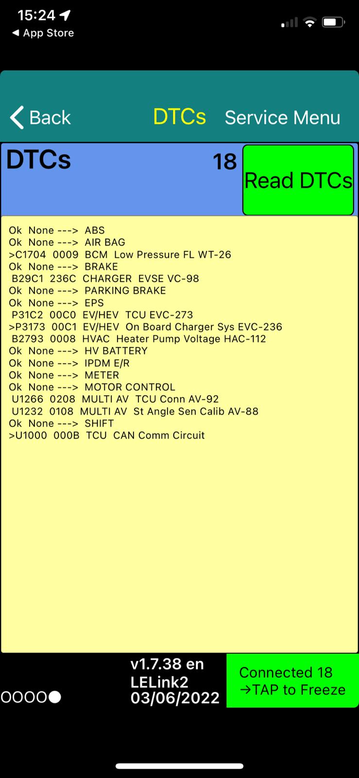
3NA6A sticker on charger appears to have software update to 3NA7A as recognized in LeafSpy Pro

Just in case I missed an important step, I didn't try clearing DTCs and retry charging before taking everything apart and removing the OBC boards. The local dealer may or may not have attempted this when they gave a quick and dirty diagnosis for "needs OBC replacement".

*That being said, I cannot find any point of failure on the boards.*

OMrr80i.jpg


ghAGk0I.jpg


I have been using a Duosida cord style evse at home and have charged exclusively at home on same cord for 3 years we've owned it. Just noticed it wasn't charged one morning and can't point to any obvious power/weather event. After OBC charger failed, I tested on L2 at dealer (not working), DC chademo - working. Failed test/Not a candidate for the diode quick and dirty solution. Symptoms are first light blinks, typical starting clunks and then quits after about 5 seconds - this set of symptoms frequently points to a failed section of the lower board for which I can't find any failures.

For 3 days, I've combed the delightfully detailed posts from so many helpful experts here, especially @nlspace, but my exact symptoms only match a few others who managed to obtain alternate units and didn't follow up repair of their bad chargers. It would be great to fix this one because the dealer replacement option is on backorder with no ETA.

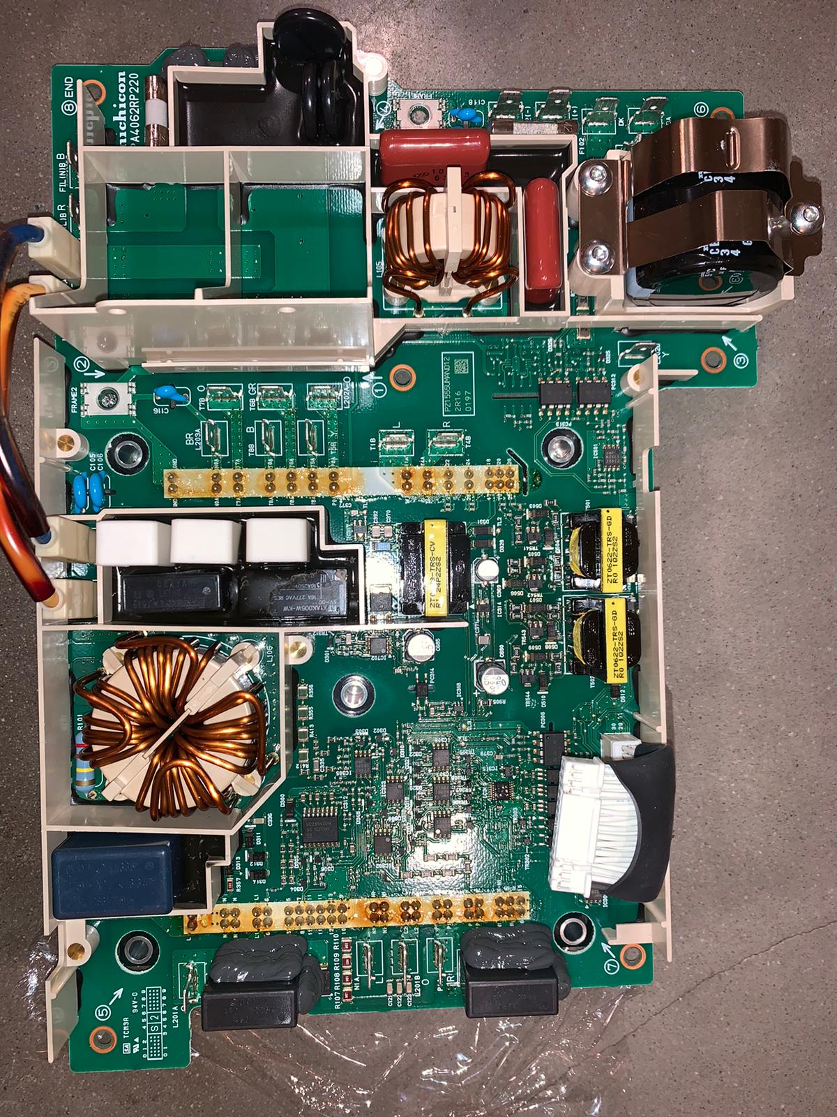
My charger boards appear to have no physically damaged components. I've used the test equipment I have to provide all the other notes below which so far seem clean - but I hope an expert can detect an error I might have made. There does not appear to be any physical damage to the waffle plate. There was no smoke residue anywhere inside the charger or on any board, etc. There are no unusual odors etc. No hot spots on the boards neither.

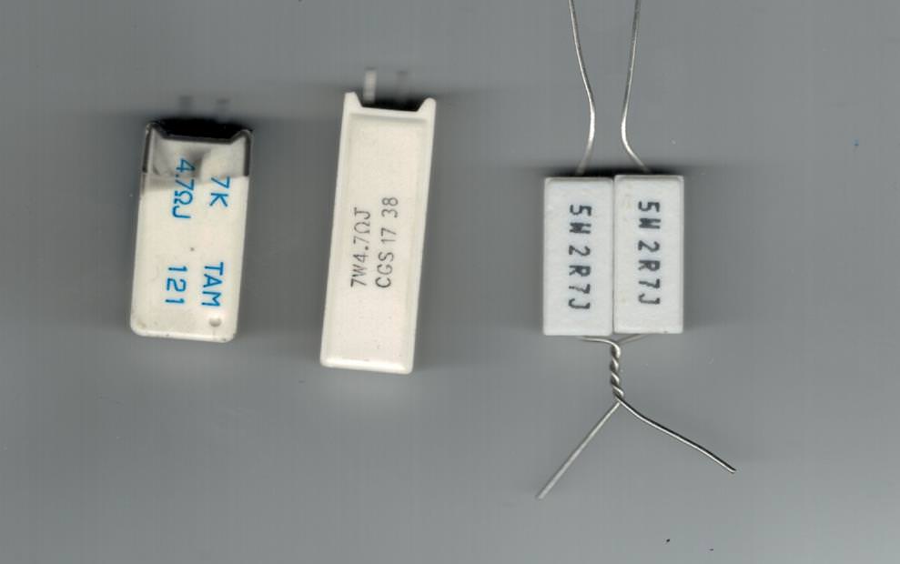
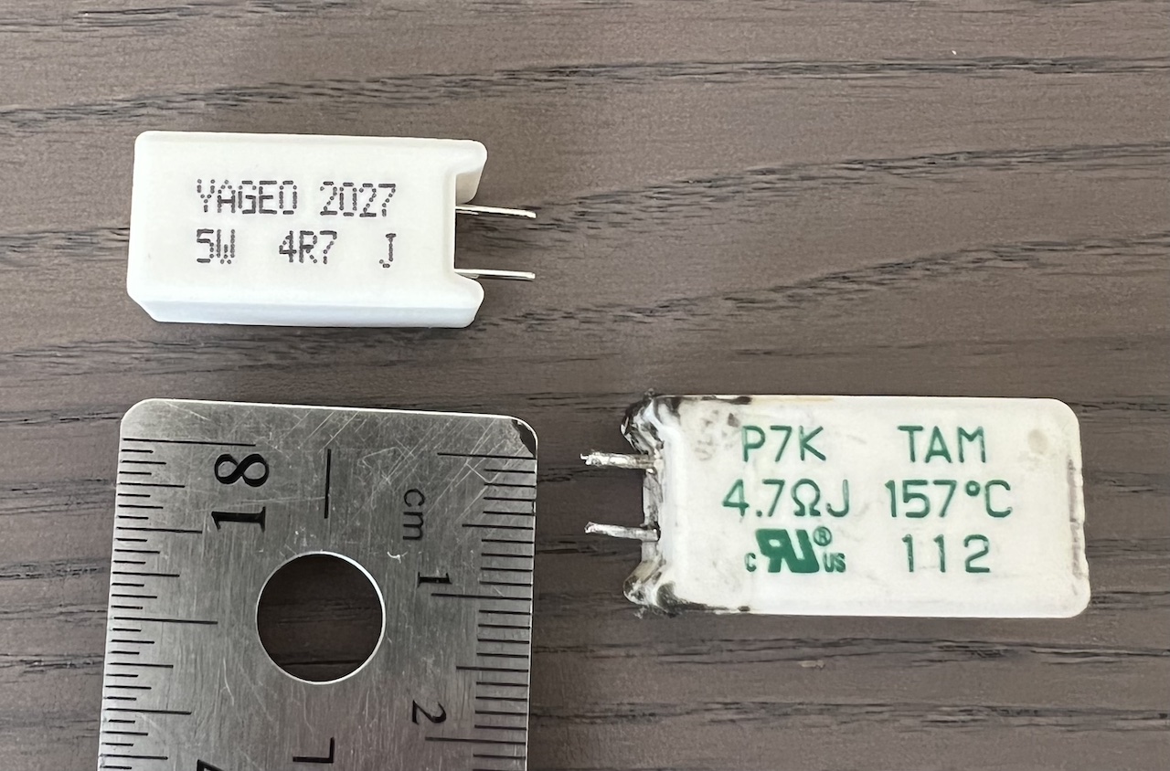
I can visually verify the power resistors, relay and LE105 capacitor as intact, but I don't have a test procedure for them. Somewhere I think I read a method to check the fused resistor in the white power resistor with green text from external pins but I cannot find it now. For now I will list these as known unknowns.

***Known Unknowns*** :
3 white power resistors (appear fine),
LE105 capacitor has a very very very slight bulge. A local electronics guy thought it looked fine - unable to test as yet.
waffle board (looks fine, need test procedure referenced in some posts)

Here I have excerpted @nlspace testing advice I gathered from multiple posts to present the test procedure and my results together. (Thank you @nlspace for your many contributions and explanations.)

Tested Components:

Diode above 4 resistor series (R107 R108...) -
:::pretty sure this one is okay :
In diode test mode, open in 1direction of polarity, .63Mohm in the other.
In resistance mode, appears to be charging capacitor and resistance is increasing and .63Mohm fixed in other polarity.

A) Does your big L201 inductor have continuity or might it be blown also? Measure for continuity between the two orange wires leading to the inductor. It should read a very low, close to zero Ohms if okay.
:::Measured 0.35 ohms

B) Is the big 2700uF capacitor okay or might it be shorted? Measure the capacitor between the red and black wires. If it reads close to zero ohms then it is shorted
:::Measured 5K ohms and climbs rapidly

C) There are 3 fuses on that board that need to be checked for continuity also. F101, 102, 103.
:::
F101 (Ceramic) good
F102 (glass with sand) good
F103 (glass held by RTV) good

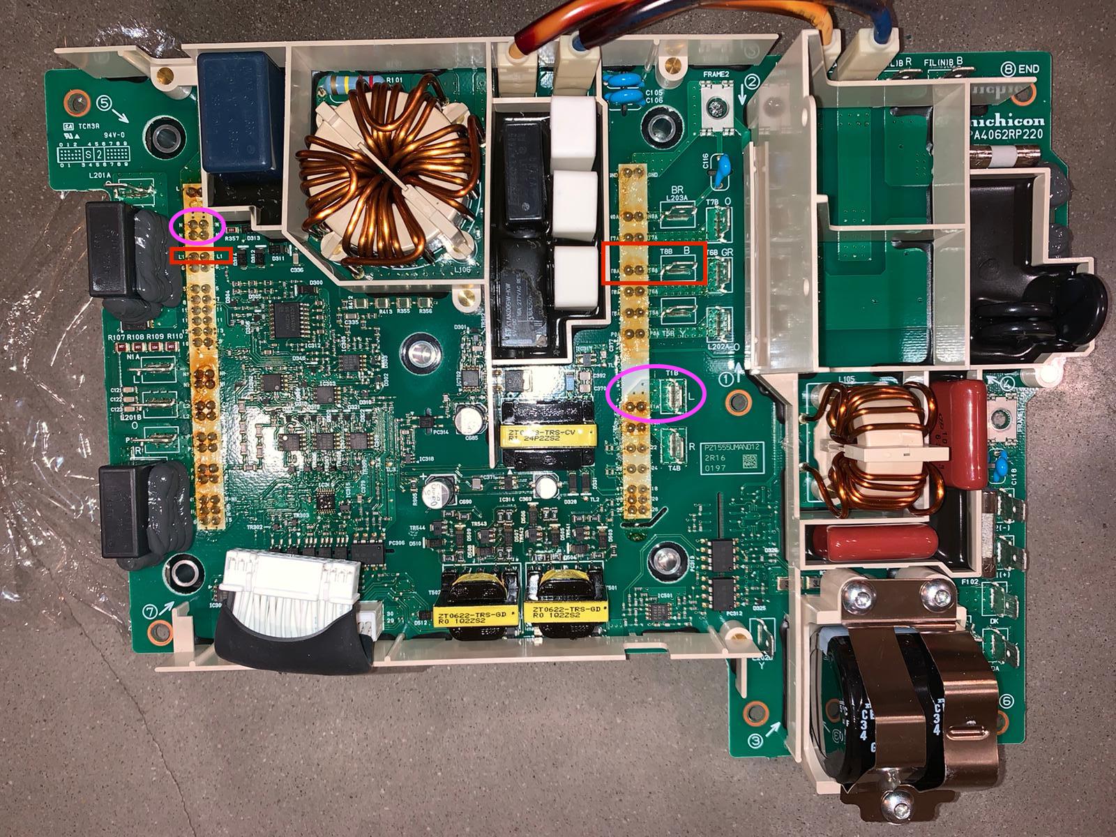
D) Measure for resistance between the solder junctions labelled "8" and "7" on the seventh row down on the left hand side.
:::0.2 ohms ? What does this mean

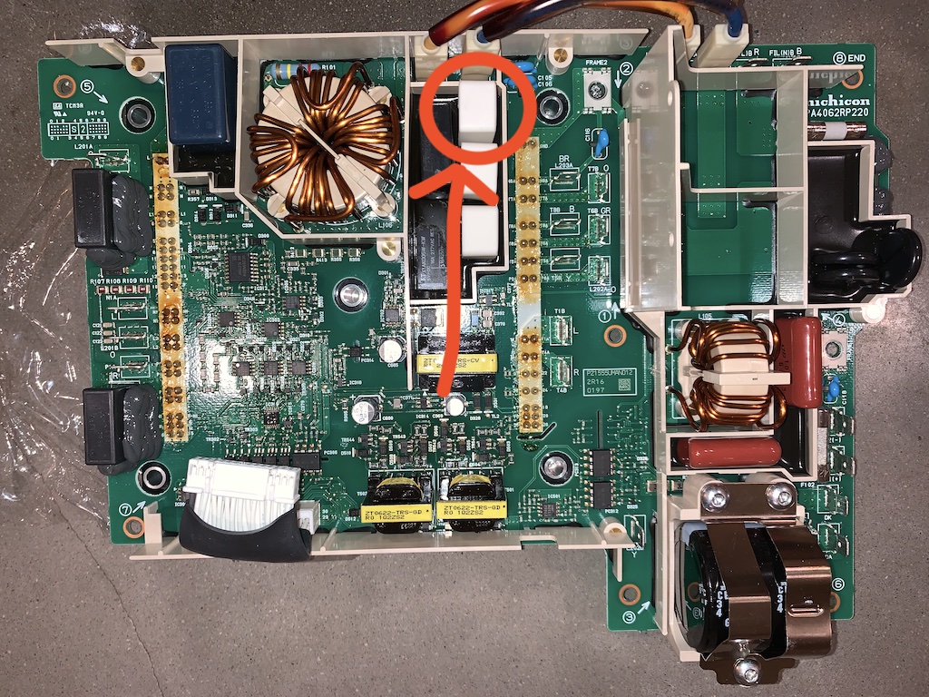
E) check for continuity on the those black nickel-sized lollypops next to the fuses in the black potted area.
:::No continuity on any of 3 lollypops - what should be expected here?

F) Also check continuity across that little glass tube (lightning arrestor) next to that.
:::No continuity

G) Do you still have the OEM level 1 version EVSE?
:::no, never had

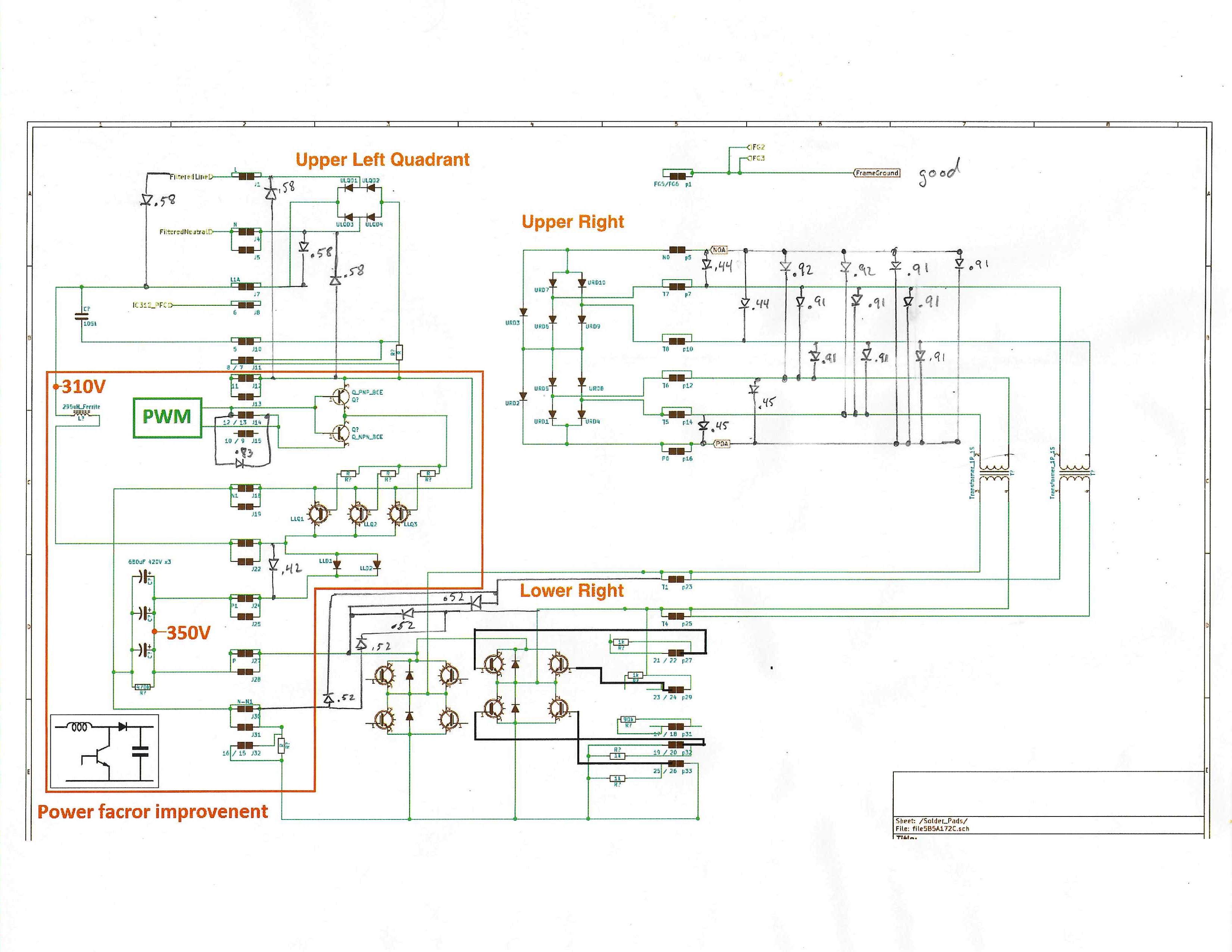
H) When you pull the board there are some diode voltage checks that you can do to make sure the waffle plate is not damaged.
:::Does someone know the link to the frequently referenced tests?

I) On the top board, D547 is a double diode pair.
:::Tests OK.

J)And just to double check, are the N1 and P1 pins on the left side shorted to the T1 and T4 pins on the right hand side of the waffle plate?
:::In diode test mode, N1 is shorted to T1A and T4A in one direction (N1 shorts to P1 in this same polarity), and P1 is shorted to T1A and T4A in the opposite direction.

K) You should probably check the diode drops of the waffle plate to make sure that it is not shorted/damaged, especially the AC rectifier section and the PFC.
:::I think this is a reference to same as H) above.

L) large 300µF cap in lower right
:::resistance climbing, no shorted

Can anyone point to what I might be missing?
 
Here are a few ideas for you.

Verify that you have a good strong starter battery. An old, weak or worn out 12V battery will cause multiple faults, especially the U1xxx DTCs such as you show in you post. Those are CAN buss related DTCs that may be due to a weak 12V battery and are preventing charging. Disconnect the 12V and take it to get load tested, then if good charge it using a smart charger to get it up to 14.4 and desulfate the plates and get it fully charged. If it doesn't pass, replace it with a new one and charge it fully before putting it back in. This should reset the DTCs and you can make a clean slate when you try charging the pack again with an EVSE. But before you try again, go ahead and check the board since you have it out.

In diode check mode on a multimeter aka DMM, the reading is in volts, e.g. 0.5 to 0.7 volts is the forward conducting voltage at which the diode just turns ON and is an indication that it is likely okay. Reversing the leads will show 0. or no voltage since a normal good diode will block current in the reverse direction.,

Here's the answer for "H)":
If you rotate your board in the photo CW to the right, then the writing will be easier to read and align with the drawing of the waffle plate solder connections as shown in this diagram,
WP diagram

Check the diode drops within the waffle plate at the solder junctions as shown above; the forward drop voltages can be compared to these diode drops.

Also check the resistance across the 3 ceramic tombstone resistors because maybe the internal thermal fuse has blown. To do this measure from the white wire faston tab terminal over to the waffle solder junctions labelled "N", it should read about 15 Ohms (i think they are 4.7 Ohms each, but its been awhile since i looked at that board). Also check from the Black wire over to the solder pair labelled "L", it should be less than 1 Ohm (like a direct connection short circuit).

For "D)":
The resistance reading between "7" and "8" is the current sense resistor buried inside the waffle plate; it is a very small value such as you measured (okay), but if it were blown then you would have read open circuit (really high or infinite reading).

All the rest of your readings are as expected (good).

i suspect a weak 12V until it is proven to be good and strong, seen a lot of issues over the past 2 years due to that.
 
I appreciate the quick reply and look forward to pursuing your suggestions. I had forgotten to rotate the picture before I sent it to Imgur, but I do know the orientation you are referring to, so I can use that for discussion. Just rior to disassembly, I had hooked up the battery from our other car with jumper cables (while turned off) and had experineced the same result, but because I had not disconnected the gel cell from the leaf, then nothing would have been cleared out, and because the other car wasn't running, there wouldn't have been a change in voltage. It hadn't been a real thorough test just a hope of an easy fix.

When I complete the other tests you've suggested and get it put back together, I will have externally charged both battery options to try. The current 12v is a gel cell about 3 years old and has only ever been in the Leaf and never on a charger so I follow that it is a variable that must be completely evaluated.

more details soon.
 
many thank yous! Here are more test details.

Also check the resistance across the 3 ceramic tombstone resistors because maybe the internal thermal fuse has blown. To do this measure from the white wire faston tab terminal over to the waffle solder junctions labelled "N", it should read about 15 Ohms (i think they are 4.7 Ohms each, but its been awhile since i looked at that board). Also check from the Black wire over to the solder pair labelled "L", it should be less than 1 Ohm (like a direct connection short circuit).

I cannot determine the white fasten tab terminal you reference. My board does not have a white wire terminal per se--there are two white wires that come out of the potting compound in the bottom of the charger and are spliced to a single blue wire that is board location T1B and labelled "L" (for blue presumably) that is connected by a thick trace to T1A pins on the right hand group of waffle plate pins. (the Red wire connects right below and is matched to T4A pins).

Is this the right location? There is no continuity from the T1B terminal to N pins on the left side. (see image purple)
I have three black wires, is no continuity from any black wire (which is T8A) to L1 pin pair on the left side (see image red boxes)

Please clarify the locations we are talking about.

Also, I can just get to the pins of the first tombstone resistor with the green printing (the one with the fuse) and with my probes it too appears to be open. If I've got the correct pins in the previous reading, then this would correlate. There doesn't appear to be any physical changes to that resistor but if the fuse is internal then damage may not be apparent.

If that is indeed the issue with the fuse blown inside the resistor:
Is it common?
Is it likely to repeat if I replace that resistor?

Have others had success finding the matching part and replacing it without unsoldering the 72 connections.

See below for relevant photos.

Check the diode drops within the waffle plate at the solder junctions as shown above; the forward drop voltages can be compared to these diode drops.

Voltage drops were measured and included on the schematic and appear to nearly match the those of the sample, if not precisely by voltage, then certainly by relative voltage.

ZyEnXmj.jpg

MBbBKB6.jpg
 
keepitrunning said:
I cannot determine the white fasten tab terminal you reference. My board does not have a white wire terminal per se--there are two white wires that come out of the potting compound in the bottom of the charger and are spliced to a single blue wire that is board location T1B and labelled "L" (for blue presumably) that is connected by a thick trace to T1A pins on the right hand group of waffle plate pins. (the Red wire connects right below and is matched to T4A pins).

Is this the right location?
No, I don't believe so. The top right hand group of Waffle Plate™ pins are totally isolated from the rest of the circuit, by design. That's the traction battery end.

I think that the connection to the 3 white resistors is via one of the jumpers (short thick wires) at the top of your photo, probably the blue one. Blue is the international colour for neutral, though it's supposed to be sky blue. So I think that the terminal you want is towards the top right end of your photo, marked FILINB B. Nlspace may have been thinking of the iMiEV on-board charrger, which has a similar but not identical layout and wiring. If you find a little under 15 ohms from that terminal to the purpled N pins at the top left of the Waffle Plate™, then that confirms the resistors as good. Another test is to energise the relay and check that the resistors become shorted (0 ohms), but that's a bit tricky. Perhaps later.

Edit: if you don't find the 15 ohms, then it's quite possible I'm wrong about the correct spade terminal to be checking against.
 
Those white plastic connectors on the spade lug terminals are a style known as "Faston". They have an internal release mechanism such that if you hold the wire steady and then slide the connector up, then it will easily release and allow removal. If you just try to pull the wire, it will be locked and difficult to remove.

Those jumpers with Fastons at the top edge of the board are part of the input from the AC mains, Line and Neutral for a 120vac system. Those wires appeared to be White and Black to me, but coulomb correctly identified the colors as Blue and (Yellow?). The AC comes in to the board and travels thru some filtering then jumpers over to the fenced-in section with the black potting compound where the the 3 white ceramic resistors are located. Remove the Faston connectors near the potted area and measure resistance from the tab thru the board over to the solder junctions labelled "N" and also to the "L" solder junction in the column of joints over on the upper left side nearest to the circled "5" with an arrow pointing toward the solder junctions. The same labels are used on the schematic in the upper left quadrant.

i think someone made a repair by crushing the ceramic with a vise pliers and soldering the new part to a stub of the wire from inside the resistor. This was done to avoid removing the 72 solder joints holding the waffle plate. They were made by Tamura but that part of the business was sold to another company,
https://www.uchihashi.co.jp/en/fuse/. You may still be able to find them at electronics distributers such as Mouser, Digikey, etc. P10K series have the thermal fuse. An older datasheet is found here: P10K datasheet
 
nlspace said:
Those wires appeared to be White and Black to me, but coulomb correctly identified the colors as Blue and (Yellow?).
Yes, yellow. It's hard to tell with the darkening / discoloration of the tubes the wires are in, but the ends where the tubing doesn't cover the wire look dark blue and yellow to me.

Remove the Faston connectors near the potted area and measure resistance from the tab thru the board over to the solder junctions labelled "N" and also to the "L" solder junction in the column of joints over on the upper left side nearest to the circled "5" with an arrow pointing toward the solder junctions.
Just to be clear, those two Faston tabs will presumably be labelled with an L and an N in them, and you should get zero ohms L-L and about 15 ohms N-N, correct? And quite a high resistance from either L to either N. I suspect measuring from where I suggested would work much the same, and would not require removing of the Faston connectors.

[ Edit: added "where the tubing doesn't cover the wire " ]
 
coulomb said:
...
measuring from where I suggested would work much the same, and would not require removing of the Faston connectors.

That makes good sense--it is where the Black and Red wires from the feedthru in the housing come in to the board. The spade tabs on the board all have a color code for the wiring that connects to it, Blue is a "L", Yellow is "Y", Red is "R", Black is "B", etc
 
Remove the Faston connectors near the potted area and measure resistance from the tab thru the board over to the solder junctions labelled "N" and also to the "L" solder junction in the column of joints over on the upper left side nearest to the circled "5" with an arrow pointing toward the solder junctions. The same labels are used on the schematic in the upper left quadrant.

From ac input terminal L to waffleplate L there is less that 1ohm

From ac input terminal L to waffleplate N there us 0.22Mohm

From ac input terminal N to waffleplate L there is open

From ac input terminal N to waffleplate N there is open

Also, I made an extended probe and sanded the spray coat off of the pins on the back side to reach in deep and measured open on the pins that should be the resistor/thermo.

So it looks like the thermo protection fusible link inside might have failed. Does the top side pins test results above confirm this?

It looks like that resistor / thermo combo is P/N P7K4R7J15 maybe from one Japanese manufacturer Uchihashi
http://www.kaimori.cn/d/file/wendubaoxiansi/else/pdf/shuinidianzu/fuBXSdianzuqi/P7K.pdf
https://www.uchihashi.co.jp/en/fuse/p7k/

It doesn't look like anyone sells that one or anything similar. What would be recommended for replacement? A regular power resistor?

Is this a common point of failure and does it point to a more serious issue like coolant problem?

Have others replaced this component and if so, what was used for the replacement?
 
It might work but i would keep looking for a 10W version with the proper lead spacing, the OEM is 7.5mm and the Mouser is 5mm.

The internal thermal fuse opens if the temperature exceeds the set point (157 C). A wax pellet melts and releases a spring to open the circuit. It is a safety feature to keep from blowing something. Maybe it failed due to defective wax, etc., but it could have failed if the AC relay or drive circuit had a problem that kept the resistor under load for too long.

This is not a common failure but it has been reported a few times, usually the resistor has cracked and shown scorch marks and evidence of thermal distress.

So it is important to investigate what caused the failure; just replacing a blown fuse or component is not sufficient (this is good practice both here and for all electrical or electronic failures anywhere).

Investigate if the AC relay is defective or what may have caused it to not engage (the signal comes from the upper control board) in order to bypass the resistors and start the charging. The resistors are only used for a short time to pre-charge the big black capacitor until the relay kicks in to carry the full current.

Here is a cracked resistor along with some possible replacements that others have found,
hzlgktA.jpg
 
Post Fix Follow Up

It's been a couple weeks with the fix in place and I wanted to followup on my final notes in the hope that someone else will benefit.

In the end, the only component I could determined that had failed was the thermal fused resistor P7K series 4.7ohm in the AC input section. It doesn't show external scorching or damage. Thanks to the help of other experts, I was able to check diode drops, and continuity for the problem circuit using the methods of the previous posts.

ajmDdeE.jpg

8c0bIp3.jpg

I could not determine what might have caused the failure. I was unable to desolder the relay to determine if it was 100% functional, though I did observe the charging with the charger cover off and could confirm that it seemed to be functioning normally.

I noticed that the heat conducting grease seemed in less than perfect condition after disassembly. Is it possible that the cooling was insufficient? The grease was replaced and the system was monitored internally for temperature using an IR thermometer to check the resistors and relays near the bad one. Watching the sudden temperature changes, you can see that circuit energize briefly before clicking off again. Temperatures vary wildly all over the boards and enclosure with the cooling circuit only directly cooling the waffle plate. No temperatures above 65 C degrees were observed anywhere in the charger, so the 157 Deg C thermal failure of the resistor is unusual.

I disassembled the parts in place without removing the charger from vehicle and the coolant loop because I wasn't able to get under the vehicle well enough and originally thought I would be saving a bunch of time. Would I do it again this way? May not be worth some of the other hassles, especially with the newly applied thermal grease, in the end, the hassle probably evened out with the time savings.

To do it this way, there is one aluminum bracket holding a diode that cannot be removed because the screws fixing it are so deep under the charger, so this bracket must be bent out of the way in order to free the bottom board. I like to use an adjustable crescent wrench tightened on the bracket so that it only bends at the existing bend.
jI52ukJ.jpg


It is not possible to acquire a same or similar thermally fused resistor, so I opted for a regular ceramic resistor of similar dimensions and power.

The original P7K series had 5mm pitch and 4W rating according to datasheet https://www.uchihashi.co.jp/en/fuse/p7k/.

So I replaced it with 5W, 4.7Ohm tombstone style with the same 5mm lead spacing.
https://www.mouser.com/ProductDetai...=sGAEpiMZZMtlubZbdhIBIIfzyEGm57muIhA13/JJDBg=

7QpneXH.jpg


You can dig out the soft urethane surrounding the resistor and I pulled on it while heating the back side with high-power trigger style soldering iron that could just reach these pins without having to desolder the waffle plate.
uT3vjAm.jpg


I used Thermal Grizzly Hydronaut 7.8gram conductive grease https://www.amazon.com/dp/B00ZJSDB7W. The 7.8gram size was _only just enough_ grease with nothing to spare. At least it was easy to spread with an old credit card.

I reinserted the back board which is difficult because of the bent bracket not being easy to clear and the charger still in the vehicle, and the fresh conductive grease layer. For testing I left the charger case open and soldered a ground lead to the top board so that I could leave it tilted way out to measure temperatures and listen to the relay behind it. This must be done _very_ carefully because of the voltages inside. I used a IR thermometer to keep my distance and made sure there was nothing nearby that might bump, fall, or get dropped into the charger during operation. Then don't forget to disconnect all high-voltage during any additional work inside the box--so there was a decent amount of back and forth there. This picture is in Deg F.
WUXfbsT.jpg


I could observe the AC input circuit operating the relay and the resistors briefly and then returning to a low and stable temperature. No other components seemed to be operating at any extreme temperature.

After a few charging cycles I was ready to stake the resistor in place and used this tiny tube of neutral cure silicon to hold it in place.
https://www.amazon.com/dp/B07PKRKFKF

The charger has functioned for many more cycles with no issues. I'm keeping my fingers crossed that I won't be taking apart again any time soon. Thanks to every one who spent so much time working with me and the others whose posts help me isolate and fix the issues.
 
Thanks for posting all your steps, I have a failed OBC in my 2012 Leaf and have just started taking it apart. Upon visual inspection I have found 1 blown capacitor. Will keep looking for more failed components.
IMG_1711.JPG
IMG_1719.JPG
 
By the way, does anyone know why some wires are covered with clear plastic tubing? Is it for extra insulation?
 
Hello all, I'm dealing with the same issue.
Can anyone tell me a part no. or replacement part for...
A. Small glass tube fuse. "lighting arrestor"
B. C707 capacitor on top/small circuit board. (capacitance?)
C. C722 capacitor on top/small circuit board. (capacitance?)
 
For A. The gas discharge tube lightning surge arrestor, referenced "SA" on the bottom power board, AC Input section. See this thread for some links to replacement parts,
https://myimiev.com/threads/the-tro...r-on-board-charger-obc-thread.4079/post-46048
3357-8381b0c2f3605f56dca1f9efbd466550.data


B. C702, surface mount ceramic capacitor, on the bottom layer of the control board: i measured 900 nF. Same size (0508) and value as C703, 704, 705.

C. C722, tiny smcc, size (0306) i measured 100 nF.
3358-da608bc62548c4a9b4de7cf9fd86304d.data


Good luck let us know how it goes.
 
Last edited:
By the way, does anyone know why some wires are covered with clear plastic tubing? Is it for extra insulation?
Yes clear plastic tubing for extra abrasion protection and electrical insulation--those are HV wires on the transformers and inductors.
 
Thanks nlspace,

On further diagnostics, I have found that there are burnt/shorted transistors and resistors on both the main board and waffle board.

I've read that the CHADeMo connection still works when the OBC is damaged like this. I'm going to put it back in and take it into town to see if that works. If it does, I'll just stop and charge it, often, in to town.

If anyone has purchased a replacement OBC and would like to donate their old circuit and waffle boards, I'll take them. (I'll pay the shipping)
I'll try to repair and reverse engineer the waffle board to provide a solution for this.

Capacitors get old and dry out especially in warm conditions.
We should not have to pay thousands of dollars to replace a few dollars worth of materials.
 
IMG_20240424_180745667.jpg
This area is burnt, all of the resistors, capacitors and transistors are shorted. They lead to pins 19, 20 and 25.
T1A, T4A, 19, 20, 21, 22, 23, 24, 25 and 26 are all shorted to P terminal. it most likely burnt up all of the resistors, capacitors and transistors in this circuit. Must have been a high voltage spike to burn up the glass tube lightning surge arrestor and not the fuses.
Is the waffle plate on the i-miev identical and interchangeable with the leaf?
 
Back
Top