ripple4 said:
Can you explain this in more detail? references i can follow up on?
Oops, when I said 882 ohm resistor, I meant a 1.3k resistor that when paralleled with the existing 2.74k, makes a total of 882 ohms.
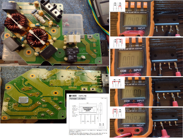
You have a resistor (d to e) that is 1.30k, so that's good. It connects to what appears to be a MOSFET, e.g. the
automotive 2SK1590. Buf if I understand your diagram correctly, it has 3.26V from drain to source, so it's not turning on. That means that the car is not yet in status/state C (see the
Control Pilot section of the
Wikipedia J1772 page). I'm surprised that the EVSE closes its contactor to provide AC to the charger; do you definitely see AC there, even if for only a minute or so? [ Edit: The half amp of charging that you see might be a measurement artifact of some kind. ]
A lot of your voltage measurements of the control pilot and related signals could well be affected by the 1kHz pilot signal. Does your multimeter have a facility for measuring peak voltages? If so, use that (or use a DSO/CRO) to find what the maximum and minimum values of the CP voltage are with respect to Protective Earth. It should be -12V at the minimum, and +9V when plugged in, and +6V when the car is ready.
But if the problem is that the G16 MOSFET isn't turning on, then things could be pretty simple. The MOSFET might be dead, failed open circuit, or it might not be getting a gate signal. Check the voltage from point b to c (I'm assuming that c is PE). There is a series gate resistor (j to k) and pull-down resistor (i to j). The j to k resistor should be about 10-100 ohms, and the pull down 22k-100k (or a wider range). If point k is staying low (same potential as c), then things get complicated, because some microcontroller is supposed to be pulling that high, if conditions are right for charging.