Adding a Brusa charger under the hood for '11/'12s

My Nissan Leaf Forum

Help Support My Nissan Leaf Forum:

This site may earn a commission from merchant affiliate links, including eBay, Amazon, and others.
I would be interested in heat rise tests of the battery when "accelerated" charging. How much does it increase compared to normal 3.3kWh charging.

I'm interested in doing this mod.
 
bowthom said:
I would be interested in heat rise tests of the battery when "accelerated" charging. How much does it increase compared to normal 3.3kWh charging.
Phil has already looked into it and published his observation. He implemented a similar mod a year ago.

Ingineer said:
The temp does rise 1-2 degrees higher, but then it drops faster, so overall I think the pack's average temp/time is less than when exposed to 3.3kW.
 
There is probably little to no extra heat generated at this capacity. We're really not talking alot here. These are (62ah?) cells so we're not even in the region of 1/4c charge rate.

1c would be nice but that would be cranking and again, it's no different then a DCQC or Chademo. Just injecting DC right into the battery but this is doing it slower which is better. :D

Charging at even Victor's rate of 11kw+ is prob not going raise pack temp much. 25kw-50kw on a Chademo.... YES! That's 1-2c rate.

LiPo's don't like that :(
 
JasonA said:
These are (62ah?) cells so we're not even in the region of 1/4c charge rate.
It's 66Ah rated capacity for the pack and 33Ah for individual cells. Strictly speaking, the LEAF does not use LiPo batteries, but similar principles apply.
 
surfingslovak said:
JasonA said:
These are (62ah?) cells so we're not even in the region of 1/4c charge rate.
66Ah rated capacity. Strictly speaking, the LEAF does not use LiPo batteries, but similar principles apply.
The Leaf uses 96 Prismatic cells/packs.. I mean its early and I'm just hitting the coffee..

EDIT: Now the coffee is kicking in----- They are LiOn cells.. same voltage. I'd like to know because I bought a few Leaf cells and they sure charge right up to 4.20 volts.

http://www.nhtsa.gov/pdf/ev/nissan_presentation-bob_yakushi.pptx
 
JasonA said:
EDIT: Now the coffee is kicking in----- They are LiOn cells.. same voltage. I'd like to know because I bought a few Leaf cells and they sure charge right up to 4.20 volts.[/url]
Oh good. I was up at 5:15 for the i3 unveiling. Lots of coffee needed. Yes, 48 modules with 66 Ah each, 96 cell-pairs, and 192 cells with 33 Ah each. The cells are lithium manganese oxide. The LiPo designation stems from the composition of the electrolyte. The LMO cells from AESC in the LEAF use LiPF6 (Lithium hexafluorophosphate), which is different from a LiPo battery. True LiPos don't have a liquid electrolyte but instead use a dry electrolyte polymer separator sheet that resembles a thin plastic film. While LMO cells theoretically reach maximum charge at 4.17V, they will readily go to a higher voltage. Even 4.3V and higher is possible. You might want to read this presentation I put together in 2011. I would recommend using the LMO acronym when referring to LEAF cells. Not to derail this thread, but would you know what the cathode material was in the LiPos you use?
 
We can always start a thread (I'm currently working on a larger pack for the Leaf) in the Batteries & Charging forum.. but to answer your question, most of the LiPo's I use are of the LiCo substrate formula.

Nano cells are the latest thing and have been proving VERY good for high C output and charge ratings but MUCH shorter life span. Remember that these cells are in the range of 30-80c+ (yes, 200-500amp draw per cell).. but they have been puffing and shooting up in resistance sky high.

Nano cell technology is just not there yet.
 
JasonA said:
We can always start a thread (I'm currently working on a larger pack for the Leaf) in the Batteries & Charging forum.. but to answer your question, most of the LiPo's I use are of the LiCo substrate formula.
There are some older threads, but it won't hurt to start something more specific on cell alternatives and replacement. If LiCo stands for lithium cobalt oxide, then that would be another difference. The LEAF uses manganese instead of cobalt, which increases safety and reduces cost. Cobalt cells reach their theoretical max energy at a higher voltage than manganese cells. They have higher energy density and lower thermal runaway, which might explain some of the RC incidents you described in your earlier posts.
 
surfingslovak said:
bowthom said:
I would be interested in heat rise tests of the battery when "accelerated" charging. How much does it increase compared to normal 3.3kWh charging.
Phil has already looked into it and published his observation. He implemented a similar mod a year ago.

Ingineer said:
The temp does rise 1-2 degrees higher, but then it drops faster, so overall I think the pack's average temp/time is less than when exposed to 3.3kW.

Thanks, I think I'll do this charger mod.
Now to save my pennys
 
Don't expect to notice any temp rise for <0.5C rate (for low R_int cells). In case of Lead that's up to about 33A charging current.
Intermittently LiMn cells can take far more that that (like well >100 A during regen) but the duration is low.

Between 0.5C and 1C you will notice 1-2'C temp rise compared to at <0.5C rate, but that rise does not impact anything.

Victor
 
JasonA said:
I'd like to know because I bought a few Leaf cells and they sure charge right up to 4.20 volts.
Where can I buy one of these modules? I saw Jeremy with one as well and I've never been able to find a discussion about them on this forum.
 
For those who're curious, I just modified my mod (can't stop messing with it :geek: )
The stock DC QC inlet got relocated under the hood where it can be used in very rare occasions
of such a need. The twist lock inlet took its place. Not it all looks very logical - as it should have
been in a first place. Works great. I Think I'll install the third booster in a couple of weeks for
completeness, and conclude this project. It's been good experience and another dive into OEM stuff.

If someone with '2013 model would want to add 10kW, it should work just as well since
the parts I tapped into are electrically the same between these models. The 6.6kW charger in
upfront now and there are no coolant lines, but if they're bought as spare parts for the 2011 model
they should fit in 2013 to provide water cooling in the back. I'm pretty sure the cavity above
the battery where tubes were mounted in '11 model did not change.

Schematics, drawings, etc are all for grabs if you want to try something similar - this is open source info:
http://www.metricmind.com/leaf/main.htm" onclick="window.open(this.href);return false;. With enough interest I may make PCBs for current sensors, but
it's very trivial to make.

Any comments - welcome.

Victor
 
gbarry42 said:
JasonA said:
I'd like to know because I bought a few Leaf cells and they sure charge right up to 4.20 volts.
Where can I buy one of these modules? I saw Jeremy with one as well and I've never been able to find a discussion about them on this forum.
I know Jeremy bought his from Autobeyours. I got mine from a yard in Sun Valley (junk yard capital of California).

I'm actually looking at a few slightly wrecked Leaf's right now (with DCQC) or.. I'm thinking about a RAV4ev and going all out on the Brusa's..

I need a bigger vehicle now that my SUV is gone and my flying gear cannot all fit into the Leaf.

VICTOR- I'll tell you right now that alot of people would be interested in that circuit for AUTO mode. I have a lot of inquires for the plate and what's going on with the CAN but your AUTO setup works pretty sweet with the adjustment you show.

Pretty slick!
 
mwalsh said:
JasonA said:
I'm actually looking at a few slightly wrecked Leaf's right now (with DCQC) or.. I'm thinking about a RAV4ev and going all out on the Brusa's..

You run across any junked '13s yet? Could do with spending less than $90 for that passenger side sunvisor.
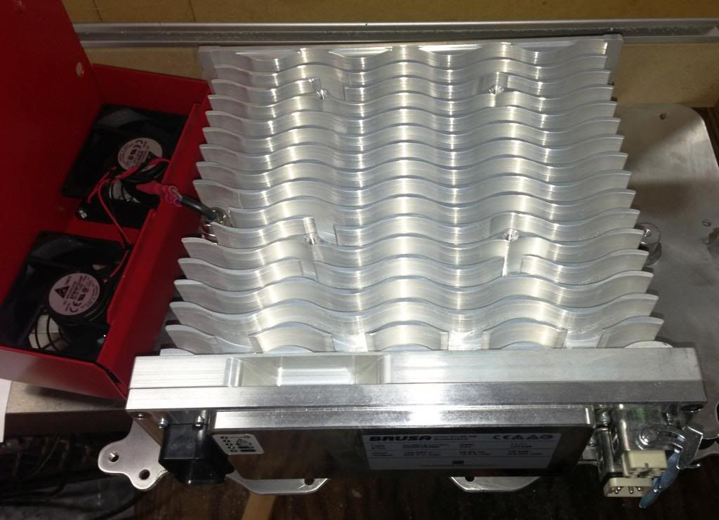
nope, 11's and 12's..
 
Trying to complete the final assembly, and running into the problem I knew was coming.

Mounting the Brusa to "the" plate.

If I mount it from below w/ flat head 6mm screws Before I mount the plate to the car, then there are plate mounting screws that I now cannot access because they are covered with charger.

This leaves mounting from above.
I have thought about this for months, and the time is here.

My original plan was to cut a hole in my plate to provide relief for the circuit board, and then make a second plate, mount the Brusa to it, and use it to cover the hole, and attach it to the lower plate along it's accessible perimeter.

This is still viable, but I'm leaning towards drilling out the threads in the Brusa, and top mounting through these hole into threaded studs on my plate.

I am concerned about heat.
We are learning that these chargers produce serious heat, and the whole aluminum base is a heat sink.
If I flat mount the Brusa to the second plate, it will be more thermally coupled to the inverter than it will be if I stand it off even 1/8".

If I try to do both, then I'm again having height problems, which I have been combating since the beginning.

Just in case you have not taken the cover off your Brusa, here is what is under there.

OOOOoooo Pretty!!!

INSIDE.jpg
 
To my eyes liquid cooled units are even prettier - they never fail to appear as eye candy for me :)
(they're smaller as well): http://www.metricmind.com/leaf/images/nlg513-wc.jpg" onclick="window.open(this.href);return false;

Back to your setup:
I should say - for air cooled units the shape or wavy fins was modeled and optimized for highest
cooling efficiency. Too dense or too curvy fins would obstruct the flow too much and reduced
volume or air passing through hurts more than larger surface area helps. Going other way
obviously also reduces effectiveness of the air cooling.

Chargers are hot because of they are small for the power they produce (high volumetric
power density), at 88-90% efficiency for 3300W produced ~350W is lost as heat.
Imagine 3-4 100 watt light bulbs crammed inside shining full blast. Of course enclosure
would get hot.

You can mount the charger up side down or fins to the flat surface other than stock cover
with fans, but you cannot leave fins exposed without cover of some sort as the air will not
be ducted through them. The charger will not get damaged, but it will get hot at lower
output power and protect itself too soon, so you will not take advantage of its power
capability. If you want to display fins, you can use plexiglass sheet to cover them...

Victor
 
Jason,

Good progress, I'm glad everything works as intended. I'm curious to see how this
will physically look when you're done.

As far as my setup - the schematic is uploaded to my blog, here is explicit link:
http://www.metricmind.com/leaf/images/098.pdf" onclick="window.open(this.href);return false;

The power meter with blue blinking lights mimicking Leaf's lights is of course
optional. All one needs is the current sensor circuit. The rest is just passive
wiring - very simple to understand how it's done.

BTW, you (and everyone doing what you're doing) can take advantage of the
BRUSA NLG513 digital I/Os to flash external LEDs to visually tell you what the booster
is doing. Same concept as Leaf's under windshield lights. You set up flashing patterns
using ChargeStar software - in automatic mode it is stored together with the profile.
Granted, you can do more useful things with I/Os like turn on and off relays (like extra cooling
for itself or whatever else you may want to do), send out status and alerts, etc.
To let people know - when these I/Os are set up as inputs, they became available
as one of conditions to transition to the next profile stage, so you can force the charger to
advance to the next stage in the profile externally by toggling an I/O (BTW this is one more
way to turn charger off - just quickly advance it through all the profile stages to the end).
Very flexible machine, people really appreciate in only when they discover what it can do.

Have fun, let me know if you need any help with charger set up or operation, I'll do my best.

Victor
 
Thanks Victor.. have some thoughts for future projects! I'm bidding on a 2012 Leaf with "slight" front/side damage but it looks fine and everything checks out, it this works, this will be my next beast with bigger packs and chargers galore!! :D

As for the Brusa's CAN we talked about that day, just so we have it right... As Jeremy said..

The "clear warnings" toggle is the one you want. It's listed as "clear error latch" bit 6 of the 618 message. Send a 1 with 0 volts and 0 amps. Comments for that message are "Error should only be cleared, when command values are zero"

This will be sent once everytime the OBC and Brusa is expected to startup and charge correct?

Thanks!
 
Back
Top