LEAF CANbus decoding. (Open discussion)

My Nissan Leaf Forum

Help Support My Nissan Leaf Forum:

This site may earn a commission from merchant affiliate links, including eBay, Amazon, and others.
Please note; I previously reported ID:x1DB : D6&D7 as "amps". That's wrong; it's D1&D2 of the data field (D1:D8). I reported the "Volts" field incorrectly also. I got "Volts" from D3&D4(upper 2 bits)... so sorry if I confused anyone trying to get the same data. Edited the earlier post.
Here's a bit more info on the CAN ID 0x1DB data. Using D1&D2 for amps and D4 & upper 2-bits of D5 for Volts
Again, I'm totally making up these scale factors but I recorded 0x1DB for an end of charge cycle with the Blink.
The Blink input power is logged via a TED device. The end-of charge shows some nice features during the equalization phase which correlate really well between my 0x1DB "Watts" and the Blink Watts. Notice the Blink (in red) is about 3700, my CAN "Watts" (blue) scales to about 3300 W. Seems possible. The CAN data was smoothed to 1-sec to be commensurate with the Blink. It's still way too noisy IMO. Possibly because I don't know what I'm looking at, or the quantization is high or something else. I think we should have a much smoother curve at the earlier, steady part of the plot.
Again apologies for the earlier errors with byte-fields.

 
For the noise in that last graph, I can think of many reasons:
1) Perhaps one or a few of the bottom bits mean something else?
2) Perhaps the sensor is noisy?
3) Perhaps the charger actually does "noise" the input signal for some reason?

As for a nice in-car UI, I've always wanted to use this thingamajig for something:
http://www.mini-box.com/mini2440v2
It's a $99 ARM with 4-inch touch panel, running Linux or Android. There's a 7" version, too, for a bit more cash.

(If you get the hardware package working, and can spiff me a copy of the hardware, I might be able to do the UI/software in exchange :)
 
I have to say a real SOC gauge is fun to watch while driving.

soc-display-1.jpg


You can really see the charge falling away on those high-speed onramps, hill climbs, and 75mph freeway runs.
The next most interesting value will be instantaneous Watts Per Mile.
 
GroundLoop said:
I have to say a real SOC gauge is fun to watch while driving.

soc-display-1.jpg


You can really see the charge falling away on those high-speed onramps, hill climbs, and 75mph freeway runs.
The next most interesting value will be instantaneous Watts Per Mile.

Considering how I get 'zapped' by my LEAF every time I get out of the car I hope you put some ESD protection on your Arduino -- my family did remind me the car is "electric" so getting zapped is part of the package!!

Maybe a wireless interface like a bluetooth shield would help with the ESD or maybe I should apply some staticide control solution to the seats.
 
Yeah, I get static-zapped when I get out of the car. It hasn't fried the Arduino, yet. :)

I did manage to short out the CAN bus once.. that shuts down the car in a hurry, but seems to leave no lasting residue.
 
Looking at CAN ID 0x1F2 reveals a "cleaner" input power-ish signature in data field D2.
Unlike the 0x1DB field which is active when sitting, driving and charging, this seems to only be active; i.e., not a constant value, when charging; ranges from 133 to 100 decimal when charging or disconnected.
Here is a plot of that field with 100 counts subtracted off with L2 charging, disconnect, L1 charging shown as a function of time (secs).
Perhaps without the 100 count bias, 33 represents 3300 W at L2 and 11 represents 1100 W at L1? In this example it took ~0.5 secs to reach '33' but on disconnect it went to '0' within one reading (no points in between).

Second plot uses this 0x1F2 field vs the TED logged power input to the Blink during last few ins of 100% charge event. Previous plot (above) of same event used the ID 0x1DB data and was much noisier with my "interpretation" of the fields.
Compares well, no?


GL,
Congrats, you get the First-Up prize.

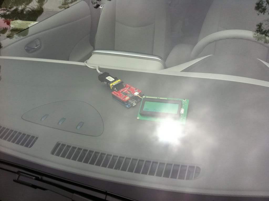
I was hoping to find a display like the ScanGauge II uses, with better visibility. Any ideas?

What display?
What interface to it?
Where to order it and cost?

Other parts, for general interest?
(narrow yellow connector thingy?)

Good Work.
 
I can't quite tell from the photo but it could also be a turn over adapter (generically called a null modem adapter in the old days)... :p

mwalsh said:
garygid said:
(narrow yellow connector thingy?)
Ooh! I can play! The narrow yellow connector thingy is a serial port gender changer. Available from places like Fry's.

And that will probably be the last contribution I can make to this thread. :lol:
 
mwalsh said:
Ooh! I can play! The narrow yellow connector thingy is a serial port gender changer. Available from places like Fry's.
:) Bingo!

Only in this case, it's a CAN Bus Gender Changer.
I have only male RJ45-DB9 housings, and the CAN Shield is male.. so. Yeah.

The RJ45 (CAT5) carries all three CAN bus signals on twisted pairs, along with power. The RJ45 housing just selects one pair to connect to the Shield.

The display is the Serial LCD 4x20 from SparkFun. Mine is defective, missing a row of pixels.

I have a (bright!) VFD 2x40 display I'm going to try next, but like most, it needs the 4-bit Hitachi/Optrex interface.

If you like the Scangauge interface, one idea would be to 'spoof' whatever K-Line signal it's looking for, and display whatever you want as water temperature etc. More work than it's worth.

I think Sparky has the right idea.. try to isolate and graph fixed elements and make specific (limited) changes to the inputs to observe. Endless logs of me driving around doesn't really add insight, since the same variables are changing all the time.

Ideally, two-person team with a laptop watching live data, driving around trying specific things in real-time.. that will probably get there the quickest.
 
I have gotten CAN-Do (ver 136) to work pretty well now.

1. Takes input from 1 to 3 live CAN buss data streams (Bin Format now)
2. Graphs selected byte of selected messages
3. Shows all the used data values in the 8 data bytes of a selected message
4. Graphs a 2-byte value, from selected bits of each, with 2's Comp negative numbers.
5. Writes and reads EV, Car, and AV message data Logs
6. Writes and reads a combined Log file, with messages from 1, 2, or 3 CAN busses.
7. Holds 20 million messages in memory
8. Runs on PC with Windows Vista, XP, and Win7

If you are interested in trying it, let me know and I will post it.
 
What is the maximum SOC value people are seeing after charge?

Mine is "281" (decimal), so I'm using that as 100% reference. It seems this is not a universal constant, though. What do you all see?
 
GroundLoop said:
Mine is "281" (decimal), so I'm using that as 100% reference. It seems this is not a universal constant, though. What do you all see?
Once I figure out what stuff I need to buy (and how to put them together) - I can check it out. My guess is that the high number I get is lower than others - since it is colder here.

BTW, is there a way I can now buy the needed stuff and connect them together, update firmware etc and get this working ? Not keen on soldering (haven't touched that in years - since I quit playing around with my tube amp).
 
We have a set of items to buy, and only three connectors to add on one
"OBD" cable and a PC (XP, Vista, etc.) and you are right in there with us.

Oh, and getting the uP flashed: We are glad to help, but it looks like you
can buy a little board and flash it yourself, for around $30 we think. We
will be testing that method during the next week and post here.

I described it and where to order the non-flash pieces in a previous post.
http://www.mynissanleaf.com/viewtopic.php?f=37&t=4131&hilit=CANbus+decoding&start=120
(the 6th post on this page).

---------------
With my latest version of CAN-Do (v137), I can create and store a "recipe" for
each variable that we discover, including values in one or two bytes of data,
combining bits of both, and being able to graph the data from a log file.
A third byte in the message may be masked and a value used to "select"
a subset of the messages to be graphed.

I can record any of the EV, Car, and/or AV CAN messages, and see selected
values in real time, on a "Dashboard". The recordings can be written to Log
files for later examiation.

-------------------
Looking at a 6-hour charging session. 2 bars to 12, I see what we guess is the
"Battery Amps" value (EV: D1 and upper 3 bits of D2, as a 2's comp signed integer)
with a LOT of noise (perhaps 20%), not what I expected.

Cheers, gary
 
mogur said:
So, I want this to be my next Leaf construction project!


How difficult would it be to take that % value readout and make a few columns that showed range at a few different parameters.

For example, battery power level value divided by 2.16153846 equals "Best38mph" range. So, battery value 281 will display 130 miles.
 
What does the "OBD" end of the grey cable look like?
Possibly a 16-wire right-angle OBD male plug?

Parts list with links directly to a good source for each part, please?

Approximate prices?

Any DIY construction steps?

We hope to have an AVR-CAN based solution working within about a week.
 
Back
Top