OpenEVSE - Open Source Charging Station

My Nissan Leaf Forum

Help Support My Nissan Leaf Forum:

This site may earn a commission from merchant affiliate links, including eBay, Amazon, and others.
Latisha said:
Hi Greg Thanks for posting you Eagle Files on the OpenEVSE site. Can you post or tell me which .hex file would best work with ALL your improvement or can you explain the necessary changes step by step for "Dummies".
The DIY through-hole board v4 works with OpenEVSE firmware 1.0.0 with ADVPWR - BTNMNU - SERIALCLI - GFI.

The power monitor circuitry is optional and is not required to operate the board for normal Open EVSE operation.
Optional power monitor components: C5, C19, R2, R9, R24, R25, R27, R28, R30, and JP2
To use the power monitoring circuitry on the v4 board requires modification of the V 1.0.0 firmware.
The power monitor circuit is based on the OpenEnergyMonitor circuitry and software library.
http://openenergymonitor.org/emon/
There are many ways to utilize the power monitor circuitry which will require custom software to be written based on the use.
The board uses ADC0 and ADC2 for the power monitor inputs, and was designed to utilize the Sparkfun SEN-11005 Non-Invasive Current Sensor - 30A, along with a 9 volt output AC to AC transformer for measuring the line voltage.

The other circuitry additions and changes utilize the same I/O pins as Chris's pre-assembled surface mount boards, so utilize the same firmware. The changes mainly address efficiency, and increased noise rejection, which should increase reliability.

Greg C.
 
chris1howell said:
bowthom said:
bowthom said:
Hello Chris,
Well I guess I'm ready, just got a J1772 w/25' cord from Leviton today. I'd like to get "open evse" parts to build up. Just how do I go about that? Looking forward to projecting. :)


Hello all,
How do I go about purchasing OPEN EVSE parts? I went to the site and they show $80 pre-programmed boards but I found no way to purchase. What am I missing?

Hi bowthom,

I added you to the list in the proper order from your original PM. Sorry I missed it...

Chris


Thanks Chris.................. My cable & J1772 are lonely. :)
 
Well, I am happy. I now have a delay timer installed with an up to 31 hour delay. I have it set for 8 hours. If I just plug in my leaf it starts charging. If I want a delay I just pulse the stop/ start switch and it starts charging after 8 hours. I can pull in and charging starts after midnight.

I charge at work to 80% so the built in charger does not work for me. When you over-ride it it charges to 100%.

Phil criticized my approach saying it should be done in the EVSE's firmware. That would be a clean approuch but I only understand hardware. This works for me and it cost less than $20.

EVSETimerjpg.jpg
 
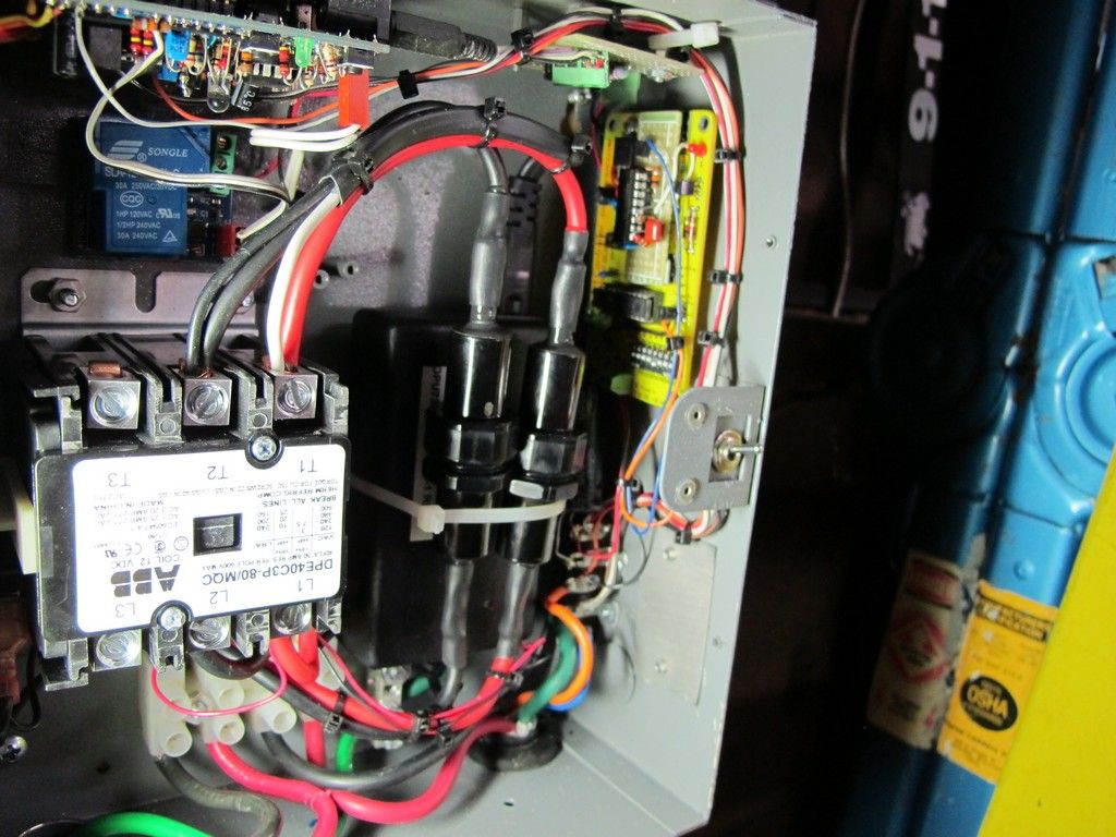
The fuse holders are Bussman Tron HEB-AA. They take a 5AG style fuse. A similar dual open fuse holder is a BM6032SQ. Both are rated for 30A 600V.
I am using some 32A 500V ceramic fuses from Ebay

The ones I used I purchased surplus years ago for $1 each.

They were commonly used as A+ fuses for high power 2 way radios. The radio shop I work at has a dusty box of them since ATO fuses have taken over.
 
Just to put it in the bank of data.

Chevy Volt with original early software + Open EVSE = no charge.

Chevy Volt with updated software + Open EVSE = charge.
 
I am Newbie to this thread.

I have looked over many of the files on the Wiki, but I have not waded through all 51 pages of this thread, so I apologize if I have missed major announcements in the middle that are not reflected in the Wiki.
I can read C++ a little, but I do not have expertise nor tools to compile code. I have built the Gid meter as well as the Quick220 design on this forum.

Hardware Requirements
I want to build a Portable version of the Open EVSE using pre-built boards and pre-loaded firmware. I also want:
Advanced Power Supply
Adafruit RGB LCD.

I understand the Advanced Power Supply is available assembled but I would have to build the Adafruit from their kit.
I understand that you are not accepting orders during October as you work down your backlog of orders for prebuilt boards.

"Portable" means I want to be able to set the current for L2 to any one of the values listed below using buttons on the unit without an external computer.

My understanding is that the current firmware (v6 ?) has defaults of 12A for L1 and 16A for L2, along with provision for changing the current setting using a serial interface to an external computer.

I also understand that the Adafruit LCD kit includes buttons that could be accessed by suitable firmware code, so no extra buttons would be needed.

Firmware Requirements
I have looked at the file MaxCurrent which appears to have prototype code for using buttons to set a current value. It appears to increment the Amp setting one Amp at a time. There is a note that the code needs an update to support current hardware. I would rather have the Amp setting state cycle through a list of values. Here is my suggested list, based upon 80% of the common breaker values for 240V:

Amp L2 list:
Amp Breaker
12 15
16 20
24 30
31 40

The list (12,16,24,31) would wrap-around to 12 if you hit the button too many times.
The Adafruit would display the selected current AMP value, at least briefly.

I appreciate that maintaining different versions of the pre-built firmware would add to overhead and hassle. One possible suggestion would be to have a removable jumper on the board to signal to the firmware whether this a portable or hard-wired unit. This way a single version of the firmware could support both applications. Perhaps there are other solutions that would fit your design better.

I understand that with the addition of a second relay with 120V coil higher current levels, including 40A, 70A, and 80A, could be supported. I guess another jumper would be needed to support the option of the 2nd relay. I am willing to forgo this option, but I would take it if it can be supported.
 
It's all already done, you just need to comment out (or in) compile time options, when you upload the Arduino sketch. All it takes is a $15-20 to programmer and a USB port, along with a download of the Arduino compiler: http://arduino.cc/en/Main/Software" onclick="window.open(this.href);return false;. You need the programmer anyway to download bug fixes and improvements to the code... OpenEVSE has been changing and improving for a while, and I expect it will continue, this is a hobbiest project, not something designed for the general public, so I don't think jumpers for options are going to happen, really... Plus there aren't any more digital I/O lines to even read jumpers at boot up that are available currently.

As far as the AdaFruit, your going to have to learn how to solder, or get someone to put it together for you. You need some electrical skills to attempt this anyway, soldering is the easiest one of them.

I have built a 30A portable OpenEVSE, and a 75A fixed OpenEVSE.

Here is the 30A portable: https://code.google.com/p/open-evse/wiki/EVSE_by_mwolrich" onclick="window.open(this.href);return false;

The "select" button is used to change amperages, you can modify the select step increment before compiling, there are seperate lists for L1 (120V) and L2 (240V)
 
mitch672 said:
It's all already done, you just need to comment out (or in) compile time options, when you upload the Arduino sketch. All it takes is a $15-20 to programmer and a USB port, along with a download of the Arduino compiler: http://arduino.cc/en/Main/Software" onclick="window.open(this.href);return false;. You need the programmer anyway to download bug fixes and improvements to the code... OpenEVSE has been changing and improving for a while, and I expect it will continue, this is a hobbiest project, not something designed for the general public, so I don't think jumpers for options are going to happen, really... Plus there aren't any more digital I/O lines to even read jumpers at boot up that are available currently.

As far as the AdaFruit, your going to have to learn how to solder, or get someone to put it together for you. You need some electrical skills to attempt this anyway, soldering is the easiest one of them.

I have built a 30A portable OpenEVSE, and a 75A fixed OpenEVSE.

Here is the 30A portable: https://code.google.com/p/open-evse/wiki/EVSE_by_mwolrich" onclick="window.open(this.href);return false;

The "select" button is used to change amperages, you can modify the select step increment before compiling, there are seperate lists for L1 (120V) and L2 (240V)
Thanks
I have downloaded the Mac version of the compiler from the link you provided. I am not used to having Mac versions of compilers. Commenting in or out compile-time options should be no problem, but what is "a $15-20 to programmer" and where do I get one ?

I don't have to learn how to solder. Many years ago I built a 35 W Heathkit mono tube amplifier, a 70 W stereo transistor Amp, a stereo tape recorder, etc. All worked as advertised.

Of course over the decades the parts have gotten much smaller, but my eyes are still pretty fair, and as I reported, I have recently done two other LEAF projects, and the Gid meter required modest amounts of soldering. The Quick220 project required no soldering, but it required some additional drills, etc. I have a good quality temperature-controlled soldering iron, vise, etc.

I have reviewed the build instructions for the AdaFruit, which look clear. I have enough experience to know that soldering all the pins correctly to the board will be a bit of a challenge, but if I can do it successfully, I should be able to complete the rest of the project.
 
The programmer required is this: http://adafruit.com/products/46" onclick="window.open(this.href);return false;

There are also clones of it on eBay, the one I linked to is also a kit, so you even have to solder it together, you can also just buy the PCB from AdaFruit ($5) http://adafruit.com/products/47" onclick="window.open(this.href);return false; and the components on your own as well (if you really like a challenge, and you might already have some of the parts)

Here is the AdaFruit info page on the USBTiny, with lots of details (construction, use. etc)
http://www.ladyada.net/make/usbtinyisp/" onclick="window.open(this.href);return false;

SparkFun also has a similar item, although I don't have experience with it: https://www.sparkfun.com/products/9825" onclick="window.open(this.href);return false;

eBay search turns up quite a few as well, can't say I have tried any of them, but I'm guessing they ship from China/Hong Kong for the most part:
http://www.ebay.com/sch/i.html?_trksid=p5197.m570.l1313&_nkw=USBtinyISP&_sacat=0&_from=R40" onclick="window.open(this.href);return false;
 
With the help of Chris Howell I was able to install a L2 ESVE for under $400.00 and still can carry around my original L1 from the dealer--I'm leasing my Leaf, so I didn't want to alter the unit.

I used to fool around with "bare bones" pc's and this project resembles that in frugality and utility. I already had a subpanel in my garage capable of 240V, so I did this without an electrician. As always, proceed at your own risk!

Chris showed some "combo boards" about two months ago on this thread. They are about the size of two key fobs--you could put them anywhere! After looking for various enclosures at home depot, I noticed my subpanel had a bit of extra space inside. Why not use it?

The price of the J-1772 http://store.leviton.com/J1772-Charge-Connector-and-Cable-Electric-Vehicle/b/5742800011 has magically come down about $100.00 and the cable seems very well built and durable.

I purchased slow blow fuses with holder and a CT from digikey which arrived in a couple of days, and the J-1772 arrived a week later. Through ebay I found some 10 g wire (which might be overkill) and heat shrink flag terminals. It took awhile to figure out what those right angle female connectors were called :roll:

There was a problem with the prototype board which Chris fixed for me within a week--Thanks!

The assembly was easy, I drilled a few holes in the back of the subpanel to mount the fuses and "combo" board. The flag terminals kept the wiring orderly:
2012-10-07+11.51.13.jpg

2012-10-10+10.10.24.jpg

The J-1772 ran through a knockout in the bottom of the subpanel, the CT surrounds the red and black wires:
2012-10-10+10.11.19.jpg
. The only other wiring is a ground to the strip of the subpanel and the pilot wire, green and orange respectively, to the screw terminals on the lower edge of the board.

I probably messed up the adafruit display, but I opened up another knockout on the side to see the LED--no reading glasses required:
2012-10-10+09.56.18.jpg


This is a homemade caddy built with scrap wood:
2012-10-10+10.11.41.jpg


I'm not sure how long it will take to recoup the cost of this project in improved charging efficiency (four fillups for my SUV), but the convenience factor is great, and I never liked how the dealer provided L1 hung from the outlet. In fact, I haven't taken it out of the bag for the last two weeks.

If you are comfortable with circuit breakers, this is a very doable project. You'll just have to convince Chris to build you a combo board!
 
Your photos were too small for details. I have built 5 units and sold one. I remain very happy with my EVES's. They charge my Leaf every time and the cost is well below half the cost of the cheapest commercial unit.

I sold my Levitron unit at cost and spent about $400 to replace it. I have since rebuilt it to have a color display and a 50A heavy duty contactor. The beauty of the OpenEVESE is that it is upgradable with full documentation.
 
jimbennett said:
Chris showed some "combo boards" about two months ago on this thread. They are about the size of two key fobs--you could put them anywhere! If you are comfortable with circuit breakers, this is a very doable project. You'll just have to convince Chris to build you a combo board!
I agree! If Chris makes any more of this particular board, it's an excellent choice - Much easier to wire up than any of the other versions, IMO. I built an L1/L2 adjustable current EVSE using one of his 'combo boards' as well and I love it! The 'all in one' board concept makes it very easy for almost anyone to wire up an EVSE at a very reasonable cost

I used a clear Pelican case to put everything in - You can see the Adafruit display through the clear case. Here's the insides with the case door open
2587544_orig.jpg


A view from the back - The short white jumper wire is the modification you spoke of that Chris worked out - It didn't charge on L2 until this jumper was installed . . . . a minor 'glitch' in the PC board
8653653_orig.jpg


A view from the front with the case closed - The chrome ring at the far right is an LED lighted selector switch for setting the various programs in the menu - You can see it lit up in the photos below. The EVSE can be set for 6, 8, 10, 12 and 15 amps for L1 charging and a similar range (up to 20 amps) for L2 charging
8605272_orig.jpg


Lit up - Ready to be plugged in
7097109_orig.jpg


Charging the car - A 2012 Mitsubishi iMiEV. Maximum current for this car is about 14 amps . . . . I usually charge at 12 amps
8559769_orig.jpg


A very worthwhile project - Mine came in under $400 as well

Don
 
Great stuff here. I am hoping that someone might be able to help.

I just built an OpenEVSE using the Arduino shield kit from Chris (Thanks by the way!). I also got the EV simulator to test and make sure its working prior to building the rest of the setup.

Here is my issue:

1. When building the Arduino shield kit I noticed that the pdf from the openevse site mentioned using 1K resistors (Br, Bl, Rd) in R1 and R20. The kit only came with one 1K resistor. The only other part left over was a blue 5 band resistor (640 I think). Is this correct or should I get a 1K resistor? I put the blue one in R20 and it seems to work except for...

2. When testing state B shows connected YELLOW, state C is Vent Required RED and D is Vent required RED. If I disable the Vent check, State C goes into charging BLUE. No idea why this is happening (maybe the wrong resistor in R20?). Anything I should check?

Thanks!
 
R1 is the OP output. It is supposed to be a 1% 1K resistor. NTE has 2%resistors that will work fine. In one unit I built I cherry picked a 1K value from a bunch of 1K 5% thin film resistors.

If you have a Fry's near you they carry the NTE line. Also most electronic parts stores carry it. The problem these days is finding a parts store!
 
GlennD said:
R1 is the OP output. It is supposed to be a 1% 1K resistor. NTE has 2%resistors that will work fine. In one unit I built I cherry picked a 1K value from a bunch of 1K 5% thin film resistors.

If you have a Fry's near you they carry the NTE line. Also most electronic parts stores carry it. The problem these days is finding a parts store!

1 word "DigiKey " :)
 
Well, I moved the resistors but still cannot get into state C without disabling the Vent check. Any ideas? Thanks guys.
 
wilsoncat said:
Well, I moved the resistors but still cannot get into state C without disabling the Vent check. Any ideas? Thanks guys.

Solved it! Bad solder joint on one of the legs of the DC/DC converter.
 
DIGIKEY is great!. If you choose First Class mail for small items it is cheap. In my area there is Ford Electronics. Orvac Electronics, and of course Frys . Frys is going the Radio Shack model and dumping the geek parts.
 
Back
Top