OpenEVSE - Open Source Charging Station

My Nissan Leaf Forum

Help Support My Nissan Leaf Forum:

This site may earn a commission from merchant affiliate links, including eBay, Amazon, and others.
electronit said:
Hi Chris,
Unfortunately, I've not yet found the GFCI transformer anywhere in europe, and ordering from Digikey gets really expensive due to tax & UPS "import handling fee" (my last order of 76 euro ended up costing 116 euro in total). You don't have any lying around ? ;-)

Isn't the GFCI a requirement only in US. In Sweden there is no such requirement and electric cars are threated the same way as RVs - it is perfectly legal to connect your car directly to the grid.
 
I don't know, but I would say it is a good idea anyway (even though there's already the obligatory RCD switch in the electricity panel), and since the board supports it, it would be a shame not to implement it... And I've found a solution for the components :)
 
I received the EVSE open source PC Board and included instructions on Friday.
Chris, thank you very much.
I ordered and it is on my way a new J1772 cable assembly from TucsonEV.com, thank you Rush
 
Glad the board made it there...

Don't forget to check out the wikis on the open EVSE site http://code.google.com/p/open-evse/" onclick="window.open(this.href);return false; . They have good information and are updated as other Open EVSE builders send suggestions.

Chris
 
This topic has gotten me to thinking that what the EV world really needs is an EVSE system that can take in 200 or 400 amp service and charge 10-20 cars based on their abilities using one main controller box.

The individual cords would be buried or could be above ground. Every plug would be a 75 amp J1772 and when people plug in they'd select their preferred amperage (16, 32 or 70). A 400 amp supply line could allow for 5 teslas, 12 2013 leafs or 25 current leafs to be charging simultaneously. Additional cables could be installed for long term airport parking allowing for maybe 50 cars to be charging. It seems like at the minimum this is what all new construction projects should be installing.

It also doesn't seem like any EVSE manufacturers are looking long term for what people will need when we're all driving EVs.
 
chris1howell said:
Glad the board made it there...

Chris,

Forgot to mention it, but I got my board as well.

Will be ordering my additional needed parts soon.

Thanks,
Richard
 
My board also arrived ,all parts on my workbench awaiting final assembly...thanks for a great project kp couch
 
Would it be possible to use a "standard" Arduino Uno for this project? I guess it would need an Op Amp (and a DC/DC converter) to drive the +/- 12v PWM, but this could be implemented using a "standard" Arduino Proto Shield.

I'm a programmer myself, but often find it to be a showstopper if projects require to much "mechanical" work. :roll:
 
Blip you could use an Arduino Uno and a proto shield. Open EVSE uses the same ATMEL 328p as the Arduino. I have been planning to design a shield but have not found the time yet...

You may also be able to run the Open EVSE code with the ARDUINO bootloader, however this has not been extensivly tested.
 
Just uploaded new firmware to the Open EVSE site which was a joint effort with lincomatic...

Now default current can be changed via serial FTDI (or bluetooth serial) and saved to EEPROM without reloading the firmware.

v0.4.0
Command Line Interface (CLI)
Write Current setting to EEPROM
Serial Baud Rate 38400
CLI Commands: "show" "set amp" "save" "help"

Example:

Open EVSE
Hardware - Atmel ATMEGA328P-AU
Software - Open EVSE v0.4.0

Open_EVSE>set amp

WARNING - DO NOT SET CURRENT HIGHER THAN 80%
OF YOUR CIRCUIT BREAKER OR
GREATER THAN THE RATED VALUE OF THE EVSE

Enter amps (6-80) : 16

Current Capacity now: 16

Open_EVSE>save
Saving Settings
 
Ingineer said:
chris1howell said:
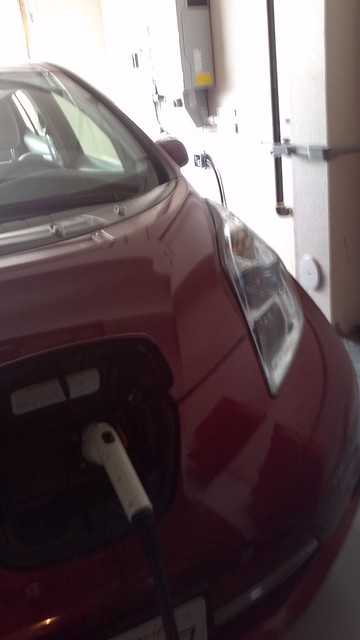
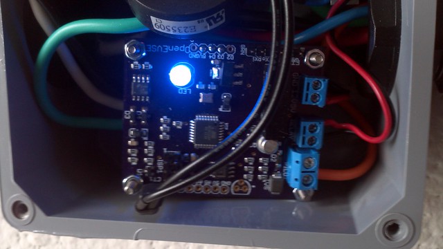
This weekend I upgraded my EVSE using the latest Open EVSE board some of you are recieving. Here are some pictures of my Open EVSE...
Nice compact packaging... Good job!

-Phil

Thanks Phil... The board in the picture is stacked on top of the Power Supply I am working on. It monitors both lines past the relay and tests Ground (during self-test and while charging), Stuck relay and will tell the EVSE if it is running L1 or L2.
 
nice work Chris, so this http://www.sparkfun.com/products/10393" onclick="window.open(this.href);return false; Bluetooth board will work with the new serial command code, without much modification then? its $40, just wondering if the 2 x 16 line display with the driver board might be easier to use (well requires some code, but only costs $20 total, plus of course wiring it in). The bluetooth is nice, but I don't see much use other than setting the current once in a while (when the Open EVSE is used portably, for example at someone else's house and you might have to dial back the max current).
 
Seems like with addition a simple 3 position switch, you could easily add "on the fly" amperage switching for portable use. Use 2 port pins, and you could have say 8, 12, and 16. I suppose you could also add one led and one button and have a cyclic amp selector. Have the LED blink at different speeds or duty cycles to indicate amperage selection. After say 10 seconds of no further button presses, the current setting is written to EE. If your cabling and relays are up to the task, you might wish to consider up to an 18.5 amp setting for use on 208v. This is not widely known, but the Leaf's charger will draw more than 16a at low input voltages. This is especially useful when plugging into many offices and commercial locations that have wye type service, as you'll get a faster charge then if you limited to 16a.

FYI: I set the current limit to 16.5a in the Rev II units for "16a", because sometimes a slightly low 240v input will mean you can still deliver a full 3.84kW. I'd recommend you also "pad" your settings up to 5% for this reason.

There are almost no 208v circuits out there that can't safely handle 18.5 amps, but do so at your own risk, and as always YMMV.

I didn't feel comfortable running the Panasonic unit that "hot" for the general public which is why I didn't do this on Rev II, but it has been tested.

-Phil
 
There is a lot of ways you could change current
A 3 position switch would work
Jumpers and a resistor network to a single analog input.
Button(s)
Touchscreen
Rotary switch
potentiometer
serial

and display.
2 line LCD
color LCD
LEDs
Segment displays
Bluetooth (windows smartphone)

The focus of the Open EVSE project currently is to get the basic EVSE functions fully supported and fully J1772 compliant. Both lincomatic and I have played with many of the options above and have code in various states of maturity.

My favorite is a single button and 2 line display, Menu/settings can be selected with long and short presses of the button.
 
chris1howell said:
There is a lot of ways you could change current
...........................
My favorite is a single button and 2 line display, Menu/settings can be selected with long and short presses of the button.
I like this option....and would like to implement it to my EVSE for our EAA meetings demonstrations.
 
That would be my favorite also,single button (normally open) and a 2 x16 lcd display .Code for following conditions...power to open evse..print lcd EVSE READY....plug into car...print lcd EVSE WAITING FOR EV.....unit chging...print lcd EVSE CHGING 16A.....also print lcd total time ev pulled power.In case of a fault.....print lcd GFI FAULT...so is there enough memory in the 328p...version 4 is 17kilobytes leaving 14 or 15 kilo for additional code...I cant wait and have already milled slot in project box for lcd...will post pic...kpc :mrgreen:
 
Back
Top