OpenEVSE - Open Source Charging Station

My Nissan Leaf Forum

Help Support My Nissan Leaf Forum:

This site may earn a commission from merchant affiliate links, including eBay, Amazon, and others.
your making all of the commercial EVSE's seem subpar :) most of them do not even implement the proper J-1772 protocol fully, never do a "diode check", never even check for "ventilation required" state etc.

one idea is perhaps supporting more relay outputs, for your upcomming "stuck relay" testing, you would need 2 relays controls to do that, the relays would have the 240V in series, so if one had a stuck contact, you open the secondary relay and shutdown the EVSE (and display the proper message as well, the 2nd relay de-energizes the 240V on the J-1772 handle). Along with that, if a "ventilation" required state comes up, you could activate a 3rd relay output, to turn on an exhaust fan... yes, I know with lithium packs, it will never be needed, why do it? because you can :) could even have an input to sense if the exhaust fan is running as well (talk about a useless feature to add just because it can be done)

if you come up with another rev of the OpenEVSE PCB (or perhaps on the OpenEVSE backpack you are working on?), perhaps 3 relay control outputs in total? not absolutley required but a "nice to have" feature. Seems to be 1 TN2222A transistor, 1 1N4148 diode and 1 330 ohm resistor per relay output, and of course the terminal block as well. there would probably be space on the Arduino backpack version for this, but maybe not on the OpenEVSE PCB, as it is tiny.
 
Commercial EVSE manufactures are welcome to copy. The code and schematics are out there, all they have to do is comply with the Open Source license...

You have a good point about multiple outputs.
To detect a stuck relay only one relay is required...
To detect and then correct you would need two...
On my personal EVSE I plan to use one relay. If I get a stuck relay, I will unplug and replace the bad relay...

The power supply I am working on has a board to board connector, I plan to put the parts for a second relay on the PS board. I may also put a connection for the pilot and main relay there as well. That way all the wires are screwed into the PS board, you could remove the Main board quickly only disconnecting the CT coil (I built mine with a connector)... For those of us who need to remove the board regularly it will save a lot of time.

Ventilation required is a whole other story, almost nobody would ever use it so it would be a waste of parts, board space and valuable pins on the microprocessor (there are not many left...see below) Someone could easily add ventilation support with a small add-on board, I have broken out several analog and digital pins plus there is the i2c bus.

Reserved due to hardware restrictions Bold:
(Arduino pin names)
Analog 0
Analog 1 Pilot voltage measurement
Analog 2
Analog 3
Analog 4 (i2c)For LCDs and expansion
Analog 5 (i2c)

Analog 6 If used code will not work with DIP Atmel 328 chips
Analog 7 If used code will not work with DIP Atmel 328 chips
Digital 0 Hardware Serial
Digital 1 Hardware Serial
Digital 2 Hardware interrupt (GFCI)

Digital 3 (Future Power supply Ground monitor, L1/L2)
Digital 4 (Future Power supply Ground monitor, L1/L2)
Digital 5 Red LED
Digital 6 (Future Power supply 2nd Relay)
Digital 7
Digital 8 Blue LED / Relay
Digital 9 (PWM 500hz) cant be used for much unless you want 500hz while the pilot is on...
Digital 10 (PWM 1000hz) Pilot
Digital 11 SPI MOSI (SPI used for ISP programmer)
Digital 12 SPI MISO (SPI used for ISP programmer)
Digital 13 SPI SCK shared with green LED (shows SPI activity)
 
What pin did you use for the toggle switch between different charging rates (6A/10A/13A/16A/30A) ? Seems like only digital7 is left ? Can we keep this dedicated to that - so that different software versions remain compatible ?

ps. still waiting on my Type2->Type1 cable + Type2 socket (making my evse with a socket so I can re-use the cable for public charging points), so not much progress yet... I have ordered a nice little housing
 
Ordered directly from Bals France (couldn't find just the housing on the online shop I linked to - only complete modules - but they were prepared to sell me direct). Bals is a German manufacturer of industrial plugs / distribution boxes etc.

The cost - you don't want to know - around $110 :shock: converted to dollars - but I wanted something portable & solid, and this box is completely rubber & waterproof.
 
electronit...Reserving D7 for a button falls in the it depends category... For a single button that would be just fine. If you want 2 - 3 - 4 - 5 buttons I would use an analog pin, you could use a single pin for several buttons/switches. see a tutorial here... http://tronixstuff.wordpress.com/2012/02/29/tutorial-analog-input-for-multiple-buttons-part-two/

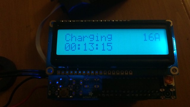
To further complicate many Open EVSE users are using the RGB LCD shield http://www.adafruit.com/products/716 to add the LCD and a buttons over the i2c bus.


It would be nice to standardize but there are just too many good ways to do it.
 
chris1howell said:
chris1howell wrote:
chris1howell said:
I built a power supply for the Open EVSE.


2012-02-16_08-53-32_176 by chris1howell, on Flickr

Chris, any idea when you might have some of these available?

I should have a basic unit ready in about 2 weeks. It is a basic 12V supply in the Open EVSE form factor.

In about a month I will have the version which includes ground check, stuck relay check, and L1/L2 detection.

I sort of procrastinated getting parts to finish my OpenEVSE build. Finally got moving on this last week and placed the orders. The transducer has come in. Had to order the relay from Newark, as Digikey was out last week (they seem to be stocked again this week).

When it came to ordering the 12V power supply, I thought to myself, I've got a bunch of those lying around. Unfortunately, they all turned out to be 120V input. Whoops. If you're ready with your version, Chris, PM me the details. It seems like a better fit.
 
chris1howell said:
electronit...Reserving D7 for a button falls in the it depends category...
I was intending to use one button to cycle over the various options (your suggestion in PM). But;

chris1howell said:
To further complicate many Open EVSE users are using the RGB LCD shield http://www.adafruit.com/products/716 to add the LCD and a buttons over the i2c bus.

That's cool - the integrated key-pad - too bad I already ordered my LCD :(
 
chris1howell said:
To further complicate many Open EVSE users are using the RGB LCD shield http://www.adafruit.com/products/716 to add the LCD and a buttons over the i2c bus.
This will be a game changer addition and the best way to operate the EVSE by NON technical users(wife).
I already ordered the LCD display with the push button switches.
I hope not to encounter problems with the code and how to implement it.
 
Don't take this the wrong way, But you guys are Killin Me Here!!

When I went to install my $1050 AV "Charger", and discovered it was just a contactor and a cord (and a couple of "bits"), I was PiSS@$d.

Promptly set out to build my own EVSE for another location on the property, and another for my beach house (The leaf should Jussst make it...hopefully)

I have a 6X6 wood-grain Hollow plastic post and cap (read Pedestal), a Tucson purchased J1772 and 25' cord, a strain relief/ gland, a couple 50 amp contactors, and thought I had figured out what my next step for a pilot signal/control board was, and then I saw this thing.

Now the project is back on hold.

I'm an engineer, and it shames me to admit this, but ........ OOoooooo.. It changes colors? :eek:

That's cool.

OK, You have put more time, energy and thought into this than I have, and I want one (at least)
Can I Get one?
How?

BTW, any source for a weatherproof(able) "bezel" for the display?

Also, if anybody hasn't ordered a J1772 cable yet, the TusconEV 30 amp unit is well made (at least as well made as the ITT), and the guy is easy to deal with.

If you need more cable, he will build it with more cable for a really nominal per-foot charge.

Please PM me or something about getting one of your controls.

Thanks
 
Actually in the end, the total cost of my EVSE will probably be over $500 all the same - so its not that "cheap" (ok - its a rediculously expensive housing, and yes the color changing lcd is maybe nonsense, but... ;) ).

However for that I (hope to) have a small, portable, solid, waterproof EVSE which allows to select the current I draw (usefull in Europe, since different countries here have different standards - 10A / 13A / 16A, and in some cases you might want to limit to 6A if you don't trust the electrical installation and have the time...). There is not currently anything like that on the market !
 
electronit said:
Actually in the end, the total cost of my EVSE will probably be over $500 all the same - so its not that "cheap" (ok - its a rediculously expensive housing, and yes the color changing lcd is maybe nonsense, but... ;) ).
However for that I (hope to) have a small, portable, solid, waterproof EVSE which allows to select the current I draw (usefull in Europe, since different countries here have different standards - 10A / 13A / 16A, and in some cases you might want to limit to 6A if you don't trust the electrical installation and have the time...).

Regarding to to the open EVSE project...... it is not all about the total price of the final equipment investment but, the pride of building something more versatile than others found elsewhere.
Without a doubt, Chris presented us with a remarkable option for a great EVSE core; unfortunately the J1772 cable assembly it is not economic now days and this is what make this project expensive and also some fancy enclosures to encase all the gear.
My outdoor fiberglass enclosure cost me $120.00 also.
 
I didn't mean to imply I thought This was a "cheap" alternative.

It's a better alternative.

And the color change display is just way too cool.

If Joe Bob Customer plugs in his AV charger, and it says fault, he's done for the day.

If we plug in one of these elegantly designed "homebuilts", and it says fault, we fix it and continue on.
I think what I'm seeing here is brilliant.
I just need one of these control boards (Color Change option please), and I'm a happy guy with a super cool EVSE.

Incidentally, As my Charge point is going to be 230' from the Breaker panel (200 of which is buried), I'm going to have my switching take place back at the panel area.
I'm placing my contactor (actually think I'll go with SSR's) box on the panel board, where it will always be in a climate controlled environment, and I also won't have an always hot 240 buried line.

I don't mind spending the $1000 for an EVSE, I just want $1000 worth of EVSE.

Thanks for all the great work.

I will wait patiently until I can buy your controller.
 
Actually, I think the open evse is proving the commercial chargers are priced in the right ballpark. Material costs, tooling, certifications, ul listing, insurance, and the standard 100% markup. It takes volume to absorb those costs we just don't have it in the ev market yet.

I agree it's about the pride and fun of building it yourself.
 
KillaWhat said:
I didn't mean to imply I thought This was a "cheap" alternative.

It's a better alternative.

And the color change display is just way too cool.

If Joe Bob Customer plugs in his AV charger, and it says fault, he's done for the day.

If we plug in one of these elegantly designed "homebuilts", and it says fault, we fix it and continue on.
I think what I'm seeing here is brilliant.
I just need one of these control boards (Color Change option please), and I'm a happy guy with a super cool EVSE.

Incidentally, As my Charge point is going to be 230' from the Breaker panel (200 of which is buried), I'm going to have my switching take place back at the panel area.
I'm placing my contactor (actually think I'll go with SSR's) box on the panel board, where it will always be in a climate controlled environment, and I also won't have an always hot 240 buried line.

I don't mind spending the $1000 for an EVSE, I just want $1000 worth of EVSE.

Thanks for all the great work.

I will wait patiently until I can buy your controller.

I'm not sure how practical that plan is, as the J-1772 Pilot signal would have to be routed be to where you placed the OpenEVSE board (you need to power the OpenEVSE board with +12 so it can't be remoted with no AC power availble), and its a low voltage signal (-12V to +12V), so you will have to run a separate conduit for Pilot and the ground reference (if you care about keeping the installation in code). I think just using the weatherproof box is fine, and don't worry about the fancy color changing LCD... those of us using that are doing it because we are building "portable" EVSEs, so we need to be able to adjust the current to the power availble where the EVSE will be used (6A, 12A, 16A, 24A etc). If you PM Chris, he should be able to put you on the list for his next build of OpenEVSE boards, that's the process we've used up to now, and it seems to work, you just have to wait until he does another run. He's also working on an OpenEVSE module that could be "stacked" on top of a standard Arduino, it might be faster to get that one, as he said he was working on the "OpenEVSE Shield" project next, along with a custom power supply he designed for the Standard OpenEVSE boards.
 
The RGB color LCD backlight is more than just cool, it is actualy very useful. You can tell the EVSE state from a great distance away.

KillaWhat... I do not have any boards in stock but I can put you on the list. I am building the boards as fast as I can. The wait is about 4 weeks. I have a large batch of parts arriving this week, so it is possible I may clear up some of the backlog...
 
chris1howell said:
The RGB color LCD backlight is more than just cool, it is actualy very useful. You can tell the EVSE state from a great distance away.

KillaWhat... I do not have any boards in stock but I can put you on the list. I am building the boards as fast as I can. The wait is about 4 weeks. I have a large batch of parts arriving this week, so it is possible I may clear up some of the backlog...

Please put me on the list!

This is the controller I want.

Re my remote switching.
I would put the control board into my "pedestal" with my J1772.
If I switch with SSR's, I can do that using TTL currents, soma little DC loss is no biggie.
And, don't hold me to this, but I believe code allows low voltage and high voltage to be run in the same conduit, as long as the low voltage wire used is RATED for the higher voltage.

I won't probably do it, because 3/4" plastic pipe is cheap, and I'd be more concerned about inductance from running along the 16 amp@240vac over onto my sensitive switching circuit..

Anyway, sign me up!
Thanks
 
Is the Arduino Uno with the LCD Display Shield and Chris' EVSE Shield the best way to get the LCD display "on" the Open EVSE?

What else is needed to complete the EVSE?
1. J1772 plug and cable
2. 240v AC relays
3. Current-sensing torroid
4. Enclosure
5. 5v DC Power
6. +/- 12v DC Power
7. Other?
 
Gary, checkout the OpenEVSE downloads page, has some example EVSEs.
Only needs +12, 100-240V input power supply, the relay needs to run on 12V, and be DPST and capable of handling the current you need, there are actually Digikey part numbers if you check the site.
The rest you have about right, on the LCD display, that just takes 4 wires to hookup,
+5VDC, Ground, SCL and SDA (I2C clock and data), these are availble on the OpenEVSE board

You could use the Arduino version (when Chris has it done), but the OpenEVSE form factor is smaller and has the same processor on it as the Arduino

http://code.google.com/p/open-evse/downloads/list" onclick="window.open(this.href);return false;

Here is the 30A max example, with a parts list required to complete it
http://code.google.com/p/open-evse/wiki/ExampleEVSE" onclick="window.open(this.href);return false;
 
Back
Top