OpenEVSE - Open Source Charging Station

My Nissan Leaf Forum

Help Support My Nissan Leaf Forum:

This site may earn a commission from merchant affiliate links, including eBay, Amazon, and others.
chris1howell said:
Gary... I have news on adjustable-MaxAmps, lincomatic has gaven his permission to include his Button Menu code in OpenEVSE. I will be releasing a new version 0.5.0, which included the additional safety features and Adafruit RGB LCD support in the next day or two. Next, I will start working on 0.6.0 to include the Button Menu code and enhancements to the Commamd line interface.

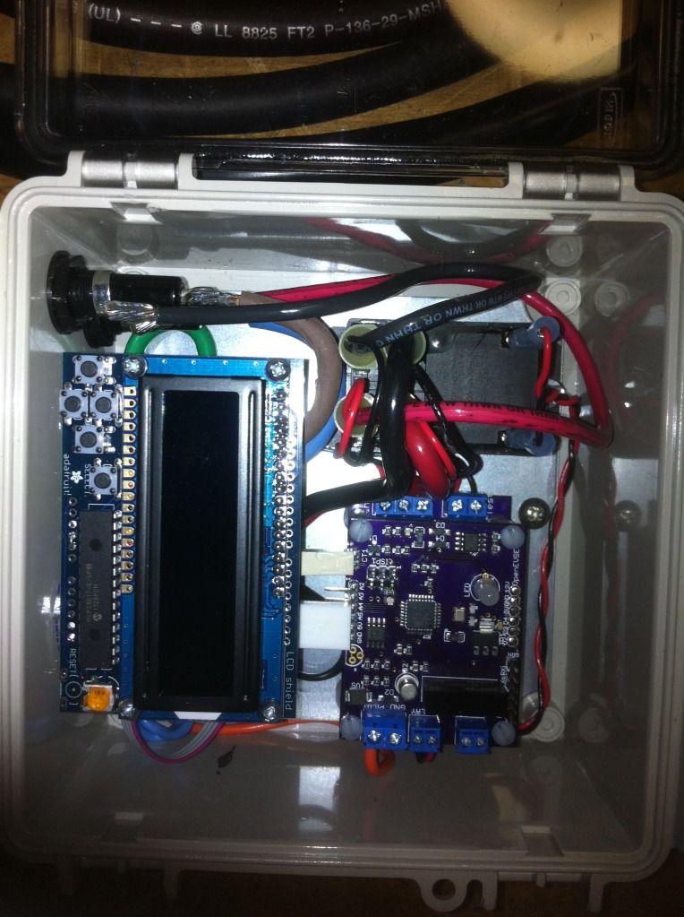
Can't wait Chris, my portable OpenEVSE is awaiting the code to test :)

Mitch

OpenEVSEassembly11.jpg
 
garygid said:
Very nice.
More detail on (and links to) the parts you used, please?

I want to do a very similar project as an adjustable-MaxAmps
portable unit, and possibly one for my garage.

Hi Gary,
The VFD is available from Adafruit and uses the Samsung 20T202DA2JA SPI interface.
http://www.adafruit.com/products/347" onclick="window.open(this.href);return false;

The only other non-standard modification is a line filter for the DC power supply.
It is a bit bigger than what is needed, but had as a spare so the cost was right.

I connected up the SPI interface on digital inputs: 3,4, and 6 using the Arduino SPI_VFD library by "Paint Your Dragon".
I based my VFD interface on mwolrich's code for the Adafruit RGB LCD Shield display on the Open EVSE Wiki.

Relay is a Potter & Brumfield T92P7D22-12 rated at 30 amps and 10 AWG supply wiring.

The box is a Carlon 8 x 6 x 4" NEMA 12/4X "Circuit Safe" Enclosure with clear door.

Hope you have as much enjoyment building your Open EVSE as I did.
Greg C.
 
Barbouri said:
A big Thanks! to Chris and the many contributors to Open EVSE.

I have finally finished my Open EVSE project that was started back in November 2011.

Charging
6943291016_0601f76ef5_z.jpg


Greg C.

That is sexy as hell, Greg. I'm hoping that soon, as people get more experience with OpenEVSE that a guide/workshop can be put together for the UN-engineers (like myself).
 
Barbouri said:
I connected up the SPI interface on digital inputs: 3,4, and 6 using the Arduino SPI_VFD library by "Paint Your Dragon".
I based my VFD interface on mwolrich's code for the Adafruit RGB LCD Shield display on the Open EVSE Wiki.

Thanks for the credit [I am mwolrich :) ], however, I did not write that code, that came from Chris, I created the Wiki, and Chris added the code to it. I have to give credit, where it's due :)
I took the pictures... Also, I have completed my version of a portable OpenEVSE as well.
the links are posted above (somewhere), to the pictures of the unit.

FYI, here is the Wiki being refered to:

http://code.google.com/p/open-evse/wiki/AdaFruitRGBdisplay" onclick="window.open(this.href);return false;
 
Hey nice,glad to see so many well completed open-evse units completed on this forum.Thanks again to Chris for a great design and for spearheading this entire effort..kpc
 
Help - EVSE Testing: I just received a new pre-assembled OpenEVSE board with GFCI stacked with the Advanced Power Supply and I can't pass the first test for State A. I just get a red led for about a second which then briefly turns Violet and shuts off. I did check the power supply voltage and it reads 12.0 volts. Any suggestions on what might be wrong?
 
Hi jjlink,

You will need to wire up the relay with the test leads connected to the j1772 side. There is a diagram in the download section of the Open EVSE site.

The reason you can not get to state a is the EVSE failed the ground check.

Chris
 
OK, Thanks

chris1howell said:
Hi jjlink,

You will need to wire up the relay with the test leads connected to the j1772 side. There is a diagram in the download section of the Open EVSE site.

The reason you can not get to state a is the EVSE failed the ground check.

Chris
 
jjlink,

this is a link to the PDF that shows the wiring diagram, in case you had any questions:

http://open-evse.googlecode.com/files/EVSEwAdvanced_Power_supply.pdf" onclick="window.open(this.href);return false;
 
Ok, Its testing good now on the bench and I understand whats going on in the diagram. My only question is on Test State "C". I am testing on a 120vac line with Ground Fault on it, which it tripping after the LED lights blue. Is this a problem, or is because the EVSE has GFI as well?

TEST State C

To test State C, with the EVSE powered connect the EV Simulator (or diode and resistor) with a resistance of 882 Ohms. The EVSE should go to the EV Connected - EVSE ready state. For Open EVSE, the LED should light Blue.

mitch672 said:
jjlink,

this is a link to the PDF that shows the wiring diagram, in case you had any questions:

http://open-evse.googlecode.com/files/EVSEwAdvanced_Power_supply.pdf" onclick="window.open(this.href);return false;
 
It sounds like it it is working as it should. To test for ground the EVSE sends a small current to ground which is why State C trips the upstream GFCI.

Thats is why the EVSE gfci coil is at the end passed the test lines.
 
I assembled the Arduino OpenEVSE shield yesterday. A fair amount of assembly work is required but the soldering isn't too bad. The sketch compiled fine after I downloaded the time.h library. I haven't really tested it thoroughly but it seems to work. The LED is green when the sketch is running and turns red when I short the 5mm terminals.

The material mentions that the shield is not well suited for actual EV charging. What is the rational for that?
 
Hi lukati..The Arduino and Shield combo should charge an EV just fine. The OpenEVSE board is recommended over the shield for a few reasons one is size and another is that not all Arduino/clones of the same quality so performance may vary. If you wish to use as your EVSE I would recommend you get a Arduino with a crystal instead of a ceramic resonator. The resonator may work but the pilot frequency will not be as stable.
 
chris1howell said:
I would recommend you get a Arduino with a crystal instead of a ceramic resonator. The resonator may work but the pilot frequency will not be as stable.
My Arduino Uno R3 seems to have a ceramic resonator, so that could be a problem. However, it looks like the older Duemilanove still has the crystal oscillator. Is the OpenEVSE shield and code backwards compatible? Thanks.
 
Gary you are correct. The Official Arduino Uno R3 has two crystals one for the USB chip and the other for the Microprocessor.

The one marked marked SPK16.000G is for USB.
 
chris1howell said:
Gary you are correct. The Official Arduino Uno R3 has two crystals one for the USB chip and the other for the Microprocessor. The one marked marked SPK16.000G is for USB.

So now I am totally confused. :? I was looking into the official Arduino Uno R3 (which is what I have) and I was reading that the Uno is inferior to the Duemilanove when it comes to demanding timing applications because they made a transition from a crystal oscillator to a ceramic resonator when they developed the Uno. So if the Uno still has a crystal for the microprocessor, why is it inferior? What I am really asking is can I use an Uno R3 for EV charging as long as it is not a clone?
 
Overview

The Arduino Uno is a microcontroller board based on the ATmega328 (datasheet). It has 14 digital input/output pins (of which 6 can be used as PWM outputs), 6 analog inputs, a 16 MHz crystal oscillator, a USB connection, a power jack, an ICSP header, and a reset button. It contains everything needed to support the microcontroller; simply connect it to a computer with a USB cable or power it with a AC-to-DC adapter or battery to get started.

The Arduino site says crystal oscillator, the UNO should work well.
 
Back
Top