OpenEVSE - Open Source Charging Station

My Nissan Leaf Forum

Help Support My Nissan Leaf Forum:

This site may earn a commission from merchant affiliate links, including eBay, Amazon, and others.
Jim:
Are we talking $70 plus about $40 shipping each for four? You have to watch for the twist when talking to the Chinese traders; does that include the UPS fees and Customs? It's difficult to pin them down to a final figure; but, sounds like a good price. I would be in for about $110.
 
7738156800_84c3ef3427.jpg


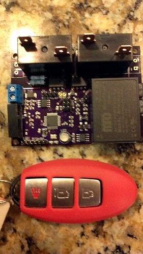
OpenEVSE + Advanced PowerSupply + Relays

I have been playing with some integrated OpenEVSE designs. This board is very small at 3.2" x 2.1" has 20A relays and the same i2c pins for LCD and FTDI pins. It Runs standard OpenEVSE code. Just add enclosure, CT, J1772 and AC plug.

I am not sure if I will make these in larger numbers but I did make 3 prototypes. If anyone wants one of the 3 for $175 with a EVsim kit and free US shipping send me a PM.

7738158028_1b35799f0c.jpg
 
I would like to time my EVSE. I would like to charge late at night. I do not want to use the car's timer since I top off to 80% when I get to work. The override button charges to 100%.

Would interrupting the pilot work?
 
You could do this nicely in software. Add a menu for the charge time (for example in steps of 1 hr, and 0 meaning no limit) - assuming you have the one-button menu, and then in the loop compare the current charge time to the limit, and set the EVSE in stopped state when past. Similarly you could implement a start delay too.
 
Maybe that would be easy for you but I am a radio tech and programming has passed me by. I only speak hardware.
 
Well, "easy" is something else :) but I've been playing around with the software quite a bit recently, and it seems something that would be do-able.

I'm quite willing to give it a go. The only problem is that my code has diverged so far by now, I'm not sure all the original stuff still works (the original advanced power code, and btnmenu_kludge - whatever that was). Perhaps I should do this on a clean version of the code - but that will be after the holidays... (I will get back the 25th of august)
 
Hi GlennD... I only speek hardware too. however the programming for arduino compatible microprocessors is within reach to anyone.

OpenEVSE currently only supports timers. You could easily stop charging after 2 hours however without external input you could not stop charging at 200am on Tuesday.

The good news is it is pretty easy to add. First you need a time source, you could do that a number of ways GPS, a network connection or a Real time clock (RTC). The easiest would be the RTC, here is a good one from Adafruit https://www.adafruit.com/products/255. Adafruit has tutorials and libraries to help out... The Adafruit would connect to OpenEVSE via the i2c port, the same port as the LCD. As long as a LCD and the RTC have different addresses they can share the bus.

I would suggust a stop at Adafruit and picking up:
RTC
https://www.adafruit.com/products/255
Arduino Uno
https://www.adafruit.com/products/50
book "Getting Started with Arduino".
https://www.adafruit.com/products/263
 
Chris, you missed condition for amps=51 in SetPWM(). Also, if you drop floats you may save yourself a few KB of code.

Code:
int J1772Pilot::SetPWM(uint16_t amps)
{
	uint16_t duty=0;	// duty cycle in % times 10
	if ((amps >= 6) && (amps <= 51))
		duty=amps*100/6;
	else if ((amps > 51) && (amps < 80))
		duty=amps*4+640;
	else if (amps == 80)
		duty=960;

	if (duty) {
		uint8_t oldSREG = SREG;
		cli();
		TCCR1A = _BV(COM1A0) | _BV(COM1B1) | _BV(WGM11) | _BV(WGM10);
		TCCR1B = _BV(WGM13) | _BV(WGM12) | _BV(CS11) | _BV(CS10);
		OCR1A = 249;
		OCR1B = (249*(duty/4)+(1000/8))/(1000/4);
		SREG = oldSREG;
		m_State = PILOT_STATE_PWM;
		return 0;
	}
	else {
		return 1;
	}
}
 
eaf said:
Chris, you missed condition for amps=51 in SetPWM(). Also, if you drop floats you may save yourself a few KB of code.

Code:
int J1772Pilot::SetPWM(uint16_t amps)
{
	uint16_t duty=0;	// duty cycle in % times 10
	if ((amps >= 6) && (amps <= 51))
		duty=amps*100/6;
	else if ((amps > 51) && (amps < 80))
		duty=amps*4+640;
	else if (amps == 80)
		duty=960;

	if (duty) {
		uint8_t oldSREG = SREG;
		cli();
		TCCR1A = _BV(COM1A0) | _BV(COM1B1) | _BV(WGM11) | _BV(WGM10);
		TCCR1B = _BV(WGM13) | _BV(WGM12) | _BV(CS11) | _BV(CS10);
		OCR1A = 249;
		OCR1B = (249*(duty/4)+(1000/8))/(1000/4);
		SREG = oldSREG;
		m_State = PILOT_STATE_PWM;
		return 0;
	}
	else {
		return 1;
	}
}


Good catch... Most of that code was optimized in the latest version at https://github.com/lincomatic/open_evse. I sent the 51A update to lincomatic.... Here is the latest version of the pilot code.

Code:
int J1772Pilot::SetPWM(int amps){  
uint8_t ocr1b = 0;  
    
if ((amps >= 6) && (amps < 51)) {    
      ocr1b = (int)(((float)amps) * 4.14F); 
      }  
   else if ((amps >= 51) && (amps <= 80)) {    
      ocr1b = amps + 159;  } 
   else {    return 1; // error  }
 
My real question, I guess, is can I just open the pilot signal or would the Leaf be unhappy with the proximity signal asserted?
 
GlennD said:
My real question, I guess, is can I just open the pilot signal or would the Leaf be unhappy with the proximity signal asserted?

Maybe... however, 0v is an error state (State E). I am not sure how the LEAF handles this condition.

The correct way to handle an external timer would be to use a digital pin on the OpenEVSE and provide 5V to enable charging and remove 5V to command the EVSE to turn off the pilot PWM. It would require a few lines of code to implement...
 
So...You have two repositories? Is code.google.com/p/open-evse the official site of the project, or is there another one?

I like this piece, it's awesome:
ocr1b = amps + 159
 
eaf said:
So...You have two repositories? Is code.google.com/p/open-evse the official site of the project, or is there another one?

I like this piece, it's awesome:
ocr1b = amps + 159

Thanks, I simplified the code a bit. We were using Amps to calculating for Duty Cycle so we could then calculate ocr1d... I used mostly forgoten algebra to simplify and solve for ocr1b directly.... I swore I would never use that silly math again :eek:.

Yes, the latest experimental - unreleased code is at github https://github.com/lincomatic/open_evse

Official releases are on the OpenEVSE site. http://code.google.com/p/open-evse/

By the way... your 51A fix is now in github
 
I think I will upgrade my home EVSE to the button version. I will then use a timer triggered by the button to pulse the button after 6 hours or so. Obviously the input will be isolated from the output to break the loop.

I will likely put it on my test EVSE to refine the design. By the way, it took the latest beta fine for the RGB display but it errors with the backpack selected.

I hear you when you say programming is easy but at 64 I was never exposed to any computer programming. I can set options with the best of you but do not ask me for anything original.
 
Well, I used a latch, a 4060, and a one shot to develop a selectable delay. It took 3 chips and an output transistor to pulse the button.

I am sure you software types could have done it in software but it works for me.

I am very happy. It works reliably for me and I had the parts on hand.
 
Announcing OpenEVSE firmware 1.0.0

Special thanks to lincomatic for lots of coding leading up to 1.0.

New features

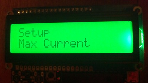
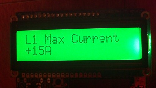
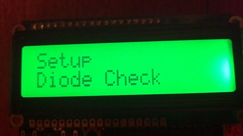
-LCD Button Menu to modify EVSE settings with button
-Button supported on A3 with 10k to GND and Adafruit RGB LCD select
-Single button navigation - Long press select; short press next
-Enhanced CLI
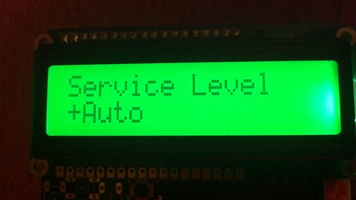
-Service Level Auto, L1, L2 (Auto requires Advanced Power Supply)
-Current settings for both L1 and L2
-Vent Required Enable/Disable CLI and LCD
-Diode Check Enable/Disable CLI and LCD
-Ground Check Enable/Disable CLI and LCD
-Stuck Relay Check Enable/Disable CLI only
-Many Bug fixes

7835994328_22d61beca6.jpg


7835992090_20145daafd.jpg


7835961914_a2d4ccba28.jpg


7835960012_f0dcbcfc23.jpg


Enhanced CLI example
Code:
Open_EVSE> 
show

Open EVSE Hardware - Atmel ATMEGA328P-AU
Software - Open EVSE 1.0.0

Settings

Service level: 1
Current capacity (Amps): 12
Min Current Capacity: 6
Max Current Capacity: 80
Vent Required: enabled
Diode Check: enabled
Ground Check: enabled
Stuck Relay Check: enabled

Open_EVSE> set
Set Commands - Usage: set amp

amp  - Set EVSE Current Capacity
vntreq on/off - enable/disable vent required state
diochk on/off - enable/disable diode check
gndchk on/off - turn ground check on/off
rlychk on/off - turn stuck relay check on/off
sdbg on/off - turn serial debugging on/off

Open_EVSE> set amp
WARNING - DO NOT SET CURRENT HIGHER THAN 80%OF YOUR CIRCUIT BREAKER OR
GREATER THAN THE RATED VALUE OF THE EVSE

Enter amps (6-16): 12
Current Capacity now: 12A

Open_EVSE> save
Saving Settings to EEPROM

Open_EVSE>
 
Chris, I received the replacement Bd. THANK YOU.
Now, I need a crash course in how to upload the new software version; I have no much experience on it.
I have installed and running = AVR Studio4 and AVRISP mkII. Connections to the EVSE are solid and powered.
Also I have installed Pony Programmer.
I downloaded the new 1.0 version and unzipped the files.
How can I do a back-up of the current file/s of the EVSE?
Witch files do I have to upload through avrstudio?
I'm using the adafruit RGB display, are all the necessary file information in withing the new rev 1.0 included? or I have to upload some other one/s?
Thank you for your help
 
Back
Top