Connecting the J1772 cable.
The actual connections are relatively simple, since there are
only 4 wires to connect. However, the physical placement,
routing of the heavy duty wires, and addition of connectors
adds to the task considerably, especially when using a small
box to contain it all.
Cable entry to the box.
The gland is large, so it requires placement so that the
external part of the gland does not interfere with the
hinges or locking tabs.
The cable passes through the gland, and the outer insulation
is carefully removed from the cable, so that the individual wires
can be routed within the box. Arranging things within the box such
that there is room for the ferrite "pipe" (if used), the Anderson connectors,
and the Current Transformer, all without overly-kinking the
big power wires (Red and Black) is a non-trivial job.
Here is a good description of using Anderson connectors:
http://www.powerwerx.com/assembly.asp" onclick="window.open(this.href);return false;
I plan to put the ferrite noise-reducing "pipe" on the wires as soon
as they enter the box, I think.
From the cable, the
1. Orange (Pilot) wire goes just a short distance, goes through the orange
Anderson connector pair, and connects to the Pilot screw terminal on
the OpenEVSE board.
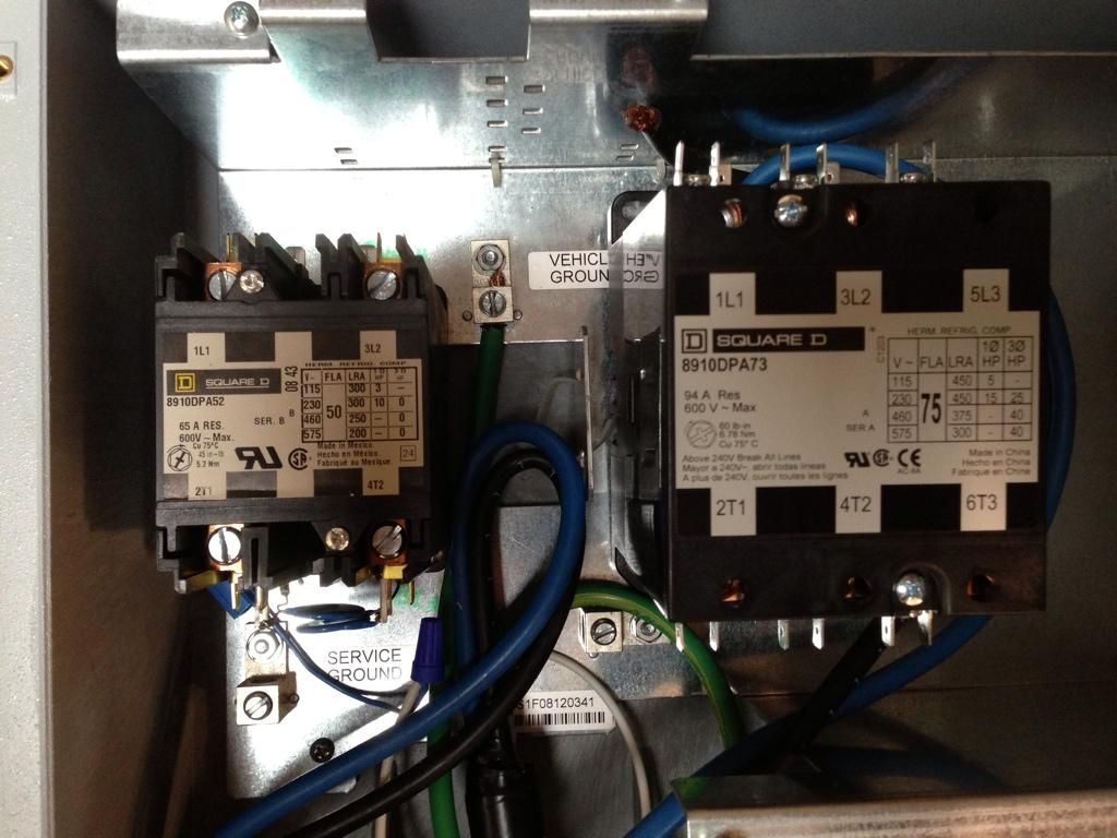
2. Red and black (power) wires should go through the red (and black)
Anderson connectors, and then connect to the relay, using the special
yellow crimp-on spade-lug connectors provided.
Note: These two power wires should pass through the center of the
Current Transformer on the way to the relay. The CT can be put on
either side of the Anderson connectors, but I think that I will try to
put the CT between the relay and the Anderson connectors.
As far as I know, polarity is not important, but I intend to connect
the black output to the black input, and the red output to the red input.
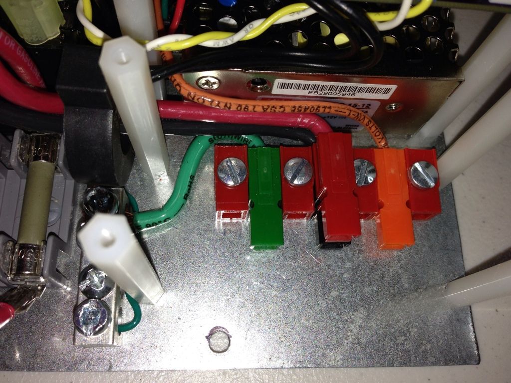
3. Green Ground wire also goes through an Anderson connector pair (green)
and it connects to one of the screw openings of the Ground Block.
-----
If you are implementing the J1772 cable pull-away safety disconnect,
the Pilot (orange) Anderson connection should pull apart immediately.
Then, the power connections should open, and finally the Ground.
I suspect that the best way to do this is to attach the inside half of each
Anderson connector pair to something solid, like the base plate.
But, as supplied, we do not have a way to attach them.
However, here is a link for the Anderson connector spacer parts.
http://www.powerwerx.com/anderson-powerpoles/housings-contacts/1399G1-1399G6-1399G2-short-long-spacers.html" onclick="window.open(this.href);return false;
Here are the pins to interconnect the connectors and spacers, we
probably need 4 pins, 2 screws and nuts, and 3 of the short spacers.
http://www.powerwerx.com/anderson-powerpoles/housings-contacts/roll-pins.html" onclick="window.open(this.href);return false;
Then we would assemble the in-box side of the connectors as one
screwed-down 4-pole connector, that the 4 individual on-cable connectors,
on different length wires, would pull out of.
I think I will try to assemble something like this (OsRsBsG) :
Orange, screw, spacer, pin, Red, pin, spacer, pin, Black, pin, spacer, screw, Green
and screw it down to the base plate. The challenge will be to find the right place
to mount this sace-consuming structure.
-----
Again, corrections please, and I will edit.


") ).
).