OpenEVSE - Open Source Charging Station

My Nissan Leaf Forum

Help Support My Nissan Leaf Forum:

This site may earn a commission from merchant affiliate links, including eBay, Amazon, and others.
Most lower current EVSE's have internal fuses. All of the 16A OpenEVSE drawings show fuses. A circuit breaker takes a while to trip unless it is a direct short. I know the stock Panasonic unit showed them in the older tear down. My Leviton also had internal fuses.

NTE sells the F fuses as a direct swap.

The EBay fuses were very cheap and I guess you get what you pay for. At my local supplier a 5 pack of Busman fuses was just under $6.
 
GlennD said:
Most lower current EVSE's have internal fuses. All of the 16A OpenEVSE drawings show fuses. A circuit breaker takes a while to trip unless it is a direct short. I know the stock Panasonic unit showed them in the older tear down. My Leviton also had internal fuses.

NTE sells the F fuses as a direct swap.

The EBay fuses were very cheap and I guess you get what you pay for. At my local supplier a 5 pack of Busman fuses was just under $6.

That may be. Sounds to me like the blind leading the blind.

The SAE J1772 specification doesn't address a need for those high current fuses. Here's the L2 diagram from the SAE document.

evsel2.jpg


Here's the hookup diagram from the OpenEVSE site. Notice how the GFI coil is on the J1772 cable side of the relay in the DIY diagram; not the same as the SAE diagram.

The DIY arrangement fails to sense any electrocution hazard due to the control circuits.

evsel2b.jpg


I could be wrong, but I think the reasoning for the fuses is...

potential hazard of shipping the OpenEVSE with firmware that allows reconfiguring the maximum current setting above the build current rating....(e.g., a 15 amp rated J1772 cord used on 40 amp circuit breaker).

For those that can't build a tamper proof current limit setting, installing fuses are a reasonable fix.
 
borland said:
Here's the hookup diagram from the OpenEVSE site. Notice how the GFI coil is on the J1772 cable side of the relay in the DIY diagram; not the same as the SAE diagram.

The DIY arrangement fails to sense any electrocution hazard due to the control circuits.
Where is there an electrocution hazard due to the control circuit?

The SAE circuit diagram you show is the obsolete J1772-2001 circuit that also included DC charging on pins 3 and 4 along with serial communications.

Greg C.
 
Fuses... if you build an EVSE that has a cord FUSE it... many use adapters on portable units, if you build a 15a EVSE and use it at a campground on a 50A circuit you will need a fuse regardless of your pilot setting. If you hard wire to the appropriately sized breaker than fuses are not required. Some may want the added protection even if hardwired.

Pilot... OpenEVSE has a setting for max current L1 and L2. If you build a 30a EVSE set the max to 30a and you will not be able to select a higher current with the LCD or CLI...
Code:
// maximum allowable current in amps
#define MAX_CURRENT_CAPACITY_L1 16 // J1772 Max for L1 is 16A 
#define MAX_CURRENT_CAPACITY_L2 30 // J1772 Max for L2 is 80A

CT placement... In general the CT should be placed as close to the source as possible. OpenEVSE implements some additional safety checks (ground check, stuck relay detection and L1/L2 auto detection) that require the CT to be placed after the test points (J1772 side of the relay). The safety checks work by sending a small current to ground. The trip point will not be correct if the CT is before. The control circuit is protected with fuses on the AC input and the test points with flame proof resistors. Everything else is low voltage DC including the relay coil. The builder has the choice do not connect the test points and you can put the CT on the AC input or connect the test points and put the CT after the relay... I prefer to have the additional safety checks...
 
borland said:
That may be. Sounds to me like the blind leading the blind.

No need for insults, this thread has been very informative and positive. I would love to keep it that way. Most builders are highly educated and very experienced. If you do not understand their design choices just ask...

borland said:
The SAE J1772 specification doesn't address a need for those high current fuses. Here's the L2 diagram from the SAE document.
True... but J1772 also does not address circuit breakers either. J1772 does reference NEC and UL. Check UL and NEC requirements for corded appliances.


borland said:
Here's the hookup diagram from the OpenEVSE site. Notice how the GFI coil is on the J1772 cable side of the relay in the DIY diagram; not the same as the SAE diagram.

The DIY arrangement fails to sense any electrocution hazard due to the control circuits.

See my previous post. The control circuit is protected by fuses and flame proof resistors. CT placement is also explained.

borland said:
I could be wrong, but I think the reasoning for the fuses is...

potential hazard of shipping the OpenEVSE with firmware that allows reconfiguring the maximum current setting above the build current rating....(e.g., a 15 amp rated J1772 cord used on 40 amp circuit breaker).

For those that can't build a tamper proof current limit setting, installing fuses are a reasonable fix.

Yes, you are incorrect. OpenEVSE implements Max current settings in software. As explained in my previous post fuses are recommended for corded EVSEs.
 
TonyWilliams said:
Is that the original Frankenplug? Did it use PLC?
I guess that it could be considered the forerunner of the "Frankenplug". Sometimes referred to as an Avcon connector, there were two configuration:
AC Level 1 and AC Level 2 - 6 pin
AC Level 1, AC level 2, and DC Charging - 9 pin

DC charging used a mandatory serial connection following SAE J1850, so no PLC.

Greg C.
 
Barbouri said:
TonyWilliams said:
Is that the original Frankenplug? Did it use PLC?
I guess that it could be considered the forerunner of the "Frankenplug". Sometimes referred to as an Avcon connector, there were two configuration:
AC Level 1 and AC Level 2 - 6 pin
AC Level 1, AC level 2, and DC Charging - 9 pin

DC charging used a mandatory serial connection following SAE J1850, so no PLC.

Greg C.

Avcon's were referred to as "The Claw"...
 
Latest DIY thru-hole OpenEVSE board Version 4.2
8437977311_28677cea78.jpg

Updated version of DIY thru-hole OpenEVSE control board.
Removed OpenEnergy power monitor header and circuitry used for power monitoring.
Added RGB LED header with current limiting resistors to support remote LED/LED's.
Board now includes reset pin connection to SPI programming header.
Changed DC-DC isolated power supply to +/- 15 vdc and added +/- 12 vdc regulators for pilot supply.
Operating the DG419 at +/- 15 vdc reduces the switches on resistance to less than 18 ohms.
Board includes 15 bypass capacitors to reduce noise and improve reliability.

I am currently working on V4.2.1 which cleans up the component labeling, adds HV isolation slots,
and an optional pin on the display header for the AdaFruit SPI VFD display.


DIY RGB LCD I2C display interface board Version 4.2
8439064322_7fab1b4404.jpg

RGB LCD display I2C interface board with RTC and battery backup. Includes header for four interface pins with ground.
Designed so that battery holder and trim pot can be mounted on either side of board.
Included pads for address selection on the I2C 16 I/O expander. Same footprint as RGB LCD board.

Greg C.
 
I just converted my work OpenEVSE to a DIY ver 4.0 unit. I did this because I wanted everything on one board.

If there is any LOCAL interest, I have a Arduino proto EVSE shield and a L1, L2 sense board free for local pickup only.

This requires an Arduino Uno programmed for OpenEVSE, A relay, A GFCI coil, a 12V power supply, an enclosure, and of course, a vehicle connector.

If no one is interested I will break it down for parts.
 
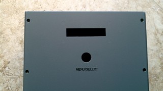
Thanks for the OpenEVSE plus kit Chris! Actually seeing the board in real life makes me realize just how small it is, it's a work of art. I appreciated very much that the display and major board components were already soldered! I have a couple questions. The first is my button isn't doing anything when pressed. I'm using the supplied jumper cable connecting ground through the switch on the NO pin. I've tested voltage, etc. and everything appears to be correct. Any tips on how to troubleshoot this?

Hopefully I didn't miss something but my LEAF is immediately starting to charge when connected to the OpenEVSE instead of obeying the charge time.

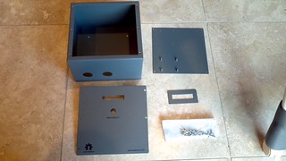
Install went well. A few tips I have. If you are going to put the button on the front, consider the length of the wire and it's position relative to the hinge so that you can open the box without worrying about it. As has been noted by others, be careful of the back plate mounting points, need enough room for the nuts.

Not sure if you are going to be building more kits but I've got some suggestions for future ones.
I only got two small screws for mounting the LCD. I also needed screws for mounting the relay and the ground bar, have enough nuts but not enough screws :)

The instructions on the site should provide guidance on the proper placement of the ferrite bead, I nearly forgot mine and then didn't have enough extra wire to loop through it a couple times. And also on where to install the MOVs. I nearly forgot these as well and ended up putting them on the OpenEVSE AC input terminals.

Additional wire connectors would be helpful. Small terminals for connecting to the button and something for attaching the current transformer. Butt connector for the ground on the MOVs.

I think there has to be some better fuse holders that don't require soldering :) Maybe these? http://www.digikey.com/product-detail/en/0031.2304/486-1745-ND/641187" onclick="window.open(this.href);return false;

Please label the version of board, for example OpenEVSE Plus v1

Throwing in a 5-15p would be nice too, for example: http://www.dale-electric.com/products/search?k=5266-C" onclick="window.open(this.href);return false;
 
If my precompiled code was used, there is version that uses a gpio input as the button input vs using adafruit button. You also need the button to enable delay timers from the menu first.
 
QueenBee,
I agree, the board is beautiful. I got mine a couple weeks ago but finally got it assembled yesterday. At first I was trying to use a smaller enclosure. My plan was to mount the relay on its side and use flag terminals so everything was nice and compact but I didn't account for the massive holes needed by the strain relieves so I threw that plan out the window.

Here are the things I ran into:
-In general, it would have been nice for more detailed instructions. Everyone have different skills so the more detailed howto the better. I thought about doing a video from start to finish but since this was my first build I figured it may get messy :)
-My LCD Button didn't work either. You have to upload firmware that supports it which I'll tackle later. I have no experience with Arduino so I'm taking it slow. I bought an FTDI Cable but I see everyone programming with SPI. Is one preferred over the other?
If you want to use the CLI on OSX:
1) Install the FTDI Driver http://www.ftdichip.com/Drivers/VCP.htm
2) Open Terminal. The remainder are terminal commands.
3) Determine the port.
ls /dev/tty.*
ex. output
Code:
/dev/tty.Bill-1				/dev/tty.Bluetooth-PDA-Sync		/dev/tty.Z310a-SerialPort-1
/dev/tty.Bluetooth-Modem		/dev/tty.Z310a-Dial-upNetworking-2	/dev/tty.usbserial-FTG7YSTI
The port is the one that looks like
/dev/tty.usbserial...
4) Connect to the port,
screen /dev/tty.usbserial-FTG7YSTI 38400
5) Type
for a list of commands. The prompt says you can also type
but that does not work.

-The two layers of my LCD did not align so they needed to be drilled out. Also the hole size on my upper board was a little small.
-The holes for the strain reliefs were larger than any step drill I had so I used a spade bit and went every slow.
-The button and the CT were done the same way. I soldered on extensions and put .1" connectors on the ends. I used the 20awg sc wire with is to stiff. I may change the button to a 3 pin header and a jumper.
-I made a drill template in sketchup which may be helpful to others.

I've been thinking about adding some form of remote management bluetooth/wifi but I'm on the fence. I'd like better flexibility in charging and maybe the RTC is all I need. I'm still thinking of the use cases and trying to balance that with the cost.
 
Chris did a great job with this latest batch. Here's mine.... Plus board and EVsim kits that arrived by mail Friday....

s58mck.jpg


Plus board and EVsim kits went together in less than an hour. I still need to assemble the RTC RGB LCD.

Here's my 240VAC bench test setup for testing functionality with the EVsim board...

2cy4f1d.jpg


There seems to be a firmware bug in version 1.06, as the board energizes the relay briefly on powerup to run the AVDPWR tests without the J1772 plug being connected to the car. Maybe this can be disabled with the menus? Later, when I get the LCD attached, I'll see.
 
I wrote a step by step guide for building the Open EVSE Plus as done at the workshop in Cerritos. It assumes that one has the basic skills needed. Send me your email and I will send it.

If Chris approves, it will go on the wiki.
 
Upon power up the relay cycles to determine whether the unit is L1 or L2 connected. It is testing for voltage or lack on the sense lines.
 
Aaron from Diversified Stage, Inc. has designed custom enclosures for OpenEVSE projects. His enclosures will be avaliable in both indoor and outdoor versions very soon at a very reasonable price. The enclosure will greatly reduce build time. They are pre-drilled for the most common parts externaly for AC/J1772, LCD cutout, Adafruit button and internaly for OpenEVSE board (with threaded standoffs), 30A relay, ground block, and fuses.


8467413440_69d91d0bd9_n.jpg

8468501058_3a3ab898b9_n.jpg

8467406191_647fcf5851_n.jpg
 
Back
Top