
You are using an out of date browser. It may not display this or other websites correctly.
You should upgrade or use an alternative browser.
You should upgrade or use an alternative browser.
OpenEVSE - Open Source Charging Station
- Thread starter chris1howell
- Start date


Help Support My Nissan Leaf Forum:
This site may earn a commission from merchant affiliate
links, including eBay, Amazon, and others.
garygid
Well-known member
The OpenEVSE Plus gives a "No Ground" message if the relay does not close?
Shouldn't this be "Relay Noop" or some such?
What message does it give when it fails to detect a proper Ground?
I guess a list of the tests, what they actually do, and
the Error messages they display would be very helpful.
Thanks, Gary
Shouldn't this be "Relay Noop" or some such?
What message does it give when it fails to detect a proper Ground?
I guess a list of the tests, what they actually do, and
the Error messages they display would be very helpful.
Thanks, Gary
dzd said:I was thinking of adding some RGB LEDs to my enclosure. Any advice on how to go about this with a plus board?
The Plus board's I/O pins are fully populated, so if you want to add LED's you need to utilize the board's I2C expansion capability. If you have the Plus board's RGB LCD option and not fully implementing the button options (Select/Up/Down/Left/Right), you could add LEDs to the unused pins (besides the firmware mods required, the adafruit RGB/LCD software library would require modifiction).
Another option would be to add another I2C board. For RGB with fancy color transitions, you might want to look at using one of ThinkM's BlinkM I2C/RGB module.

Or for simple LED on/off function, you could add a "I2C I/O expansion board", such as the PFC8574. A module like this.. is about $9 on eBay with shipping from China. Problem is these have no space for mounting LED resistors or spare pins for taking Power or common ground, just the I/O pins.

chris1howell
Well-known member
garygid said:The OpenEVSE Plus gives a "No Ground" message if the relay does not close?
Shouldn't this be "Relay Noop" or some such?
What message does it give when it fails to detect a proper Ground?
I guess a list of the tests, what they actually do, and
the Error messages they display would be very helpful.
Thanks, Gary
Yep it sure does. Remember the test leads are on the J1772 side of the Relay/Contactor, so it the relay does not close the test chips do not get power. If the test chips are not powered then the EVSE assumes there is no ground.
The AC tests work like this...
Relay Open
Read AC1 and AC2
If either is HOT then ERROR "Stuck Relay"
If neither HOT continue...
Close Relay
Read AC1 and AC2
If both Hot then set L2
If either AC1 or AC2 is HOT then set L1
IF Neither is hot then ERROR "Bad ground"
The v2 OpenEVSE board has a second relay port to enable 2 SPST relays so the tests can be done 1 leg at a time.
The logic is similar but it tests 1 relay then the other...
Other tests are:
Diode check
Vent required state
GFCI fault
chris1howell
Well-known member
borland said:dzd said:I was thinking of adding some RGB LEDs to my enclosure. Any advice on how to go about this with a plus board?
The Plus board's I/O pins are fully populated, so if you want to add LED's you need to utilize the board's I2C expansion capability. If you have the Plus board's RGB LCD option and not fully implementing the button options (Select/Up/Down/Left/Right), you could add LEDs to the unused pins (besides the firmware mods required, the adafruit RGB/LCD software library would require modifiction).
Another option would be to add another I2C board. For RGB with fancy color transitions, you might want to look at using one of ThinkM's BlinkM I2C/RGB module.
Or for simple LED on/off function, you could add a "I2C I/O expansion board", such as the PFC8574. A module like this.. is about $9 on eBay with shipping from China. Problem is these have no space for mounting LED resistors or spare pins for taking Power or common ground, just the I/O pins.
I have been thinking about building a LED only version of the RGB LCD board with no LCD. It would work without any additional code.
garygid
Well-known member
Chris,
Does the check for the test AC line being "HOT" involve
using the Ground?
How is this test done, please?
Load the hot line a bit to Ground, and look for some current?
Thanks.
Does the check for the test AC line being "HOT" involve
using the Ground?
How is this test done, please?
Load the hot line a bit to Ground, and look for some current?
Thanks.
chris1howell
Well-known member
garygid said:Chris,
Does the check for the test AC line being "HOT" involve
using the Ground?
How is this test done, please?
Load the hot line a bit to Ground, and look for some current?
Thanks.
Yes, exactly a small current is sent from each hot to ground . If current passes the opto-isolator lights a LED internal to the mid400 chip. On the other side of the chip a detector sends the output LOW when the AC side led is lit. The micro reads the state of the two mid400 chips.
So back to your original question the EVSE can't tell the diferance between an inop relay vs a bad ground. Both would result in both chips sensing no voltage on either line.
garygid
Well-known member
Great use of the opto-isolator to safely sense some current flow.
Thanks
Thanks
chris1howell
Well-known member
garygid said:Great use of the opto-isolator to safely sense some current flow.
Thanks
Thank you Gary... Your support, encouragement and advice is greatly appreciated. Without it OpenEVSE would not have been possible...
chris1howell
Well-known member
chris1howell said:Aaron from Diversified Stage, Inc. has designed custom enclosures for OpenEVSE projects. His enclosures will be avaliable in both indoor and outdoor versions very soon at a very reasonable price. The enclosure will greatly reduce build time. They are pre-drilled for the most common parts externaly for AC/J1772, LCD cutout, Adafruit button and internaly for OpenEVSE board (with threaded standoffs), 30A relay, ground block, and fuses.
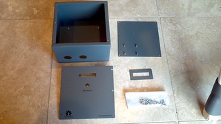
Enclosures are now avaliable. Contact [email protected].
Indoor Enclosure $58 - Outdoor $95 plus shipping and tax for CA residents...
The enclosure is very high quality and will save several hours of build time. The enclosures come with a hardware pack and a poly-carbonate LCD window.
garygid
Well-known member
Some dimensions would be helpful, at least for the box and the cutouts.
Pictures of the weatherproof version, please?
Pictures of the weatherproof version, please?
Here's my artwork for silk screening a clear cover NEMA 4X enclosure...

The silk screen masking technique quite simple. I noticed a video on YouTube.com featuring a silk screening kit sold on Home Shopping Channel. There have been several used ones for sale on eBay, so I will probably pick one up and give it a try.
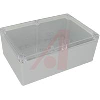
I still need to position and size the graphics, but this will be for one of the following enclosures made by Bud Industries:
PN-1340-C (6.3”x9.5”x3.5”)
PN-1341-C (6.3”x9.5”x4.72”)
The silk screen masking technique quite simple. I noticed a video on YouTube.com featuring a silk screening kit sold on Home Shopping Channel. There have been several used ones for sale on eBay, so I will probably pick one up and give it a try.
I still need to position and size the graphics, but this will be for one of the following enclosures made by Bud Industries:
PN-1340-C (6.3”x9.5”x3.5”)
PN-1341-C (6.3”x9.5”x4.72”)
chris1howell
Well-known member
garygid said:Some dimensions would be helpful, at least for the box and the cutouts.
Pictures of the weatherproof version, please?
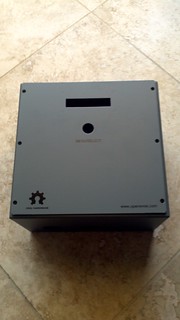
Here is a picture.
The indoor version is 8 x 8 x 5. I believe the outdoor version has similar inner dimensions but is slightly larger externally. The screws are all external to the weather seal. I have a indoor version now. Diversified Stage just shipped me and outdoor enclosure so I will have more pics in a few days.

waidy
Well-known member
Very handsome little box. Thank you for posting. I am curious of how portable the 30Amp unit with this enclosure is. Next time if you build another one or if anyone builds one, would you please reports the weight on the finish unit (either with or without the J-cable). I am considering replacing the Rav4EV supplied portable EVSE (max 240Vx12Amp) with a portable OpenEVSE (max 240Vx30Amp).chris1howell said:The indoor version is 8 x 8 x 5. I believe the outdoor version has similar inner dimensions but is slightly larger externally. The screws are all external to the weather seal. I have a indoor version now. Diversified Stage just shipped me and outdoor enclosure so I will have more pics in a few days.
garygid
Well-known member
What is the weight of these boxes?
Size of the cutouts?
Size of the cutouts?
chris1howell
Well-known member
garygid said:What is the weight of these boxes?
Size of the cutouts?
Not sure the exact weight but it is heavier than the plastic box. But it is light enough to be a portable unit.

Cable exits are 1 1/8" perfect for the PG-21 Glands. This should be fine for cables up to 30A. Over that and the hole will need to be enlarged.
http://www.polycase.com/cg-16

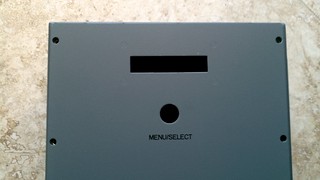
Front panel has cutout window for standard 16 x 2 LCD/RGB LCD. It also has studs for mounting. Hole is for the Adafruit waterproof buttons.
http://www.adafruit.com/products/560

Mounting plate has standoffs for OpenEVSE plus board and hold pre-drilled for fuses, 30A Relay and ground block.
Deversified stage is reccomending fuse block...
http://www.digikey.com/scripts/dksearch/dksus.dll?vendor=0&keywords=+BM6032PQ
It is about double the price but it does not require any soldering. So it will save a lot of time... If you use the enclosure, the new OpenEVSE RGB LCD (pre-built) and this fuse block. The top 3 time consuming tasks from the workshop will be significantly reduced. The tasks that took 4 - 5 hours will be less than a hour. Hopefully, we will be able to finish in a single session next time...

garygid
Well-known member
This looks like a similar fuse holder, same manufacturer, but
for a lot less $$ from Mouser:
http://www.mouser.com/ProductDetail/Cooper-Bussmann/BM6031SQ/?qs=sGAEpiMZZMtRmoYvq3OwzLPstIWsKAJ%2fD30r%2fx5HKgI%3d" onclick="window.open(this.href);return false;
Oops, this is only one pole, even though the picture shows three poles, sorry.
for a lot less $$ from Mouser:
http://www.mouser.com/ProductDetail/Cooper-Bussmann/BM6031SQ/?qs=sGAEpiMZZMtRmoYvq3OwzLPstIWsKAJ%2fD30r%2fx5HKgI%3d" onclick="window.open(this.href);return false;
Oops, this is only one pole, even though the picture shows three poles, sorry.
evnow
Well-known member
Cool. Will you make this part of your open evse order ?chris1howell said:Indoor Enclosure $58 - Outdoor $95 plus shipping and tax for CA residents...
Barbouri
Well-known member
- Joined
- Aug 9, 2010
- Messages
- 79
It is a bit less from Mouser, but you will need this one which is a 2 pole instead of the 1 pole in the original Mouser link.garygid said:This looks like a similar fuse holder, same manufacturer, but
for a lot less $$ from Mouser:
http://www.mouser.com/ProductDetail/Cooper-Bussmann/BM6031SQ/?qs=sGAEpiMZZMtRmoYvq3OwzLPstIWsKAJ%2fD30r%2fx5HKgI%3d" onclick="window.open(this.href);return false;
http://www.mouser.com/ProductDetail...2pyFaduiEUTAA0h/Q6/So7u8/H5%2bPuAE%2bwwYochU=
Greg C.
chris1howell
Well-known member
evnow said:Cool. Will you make this part of your open evse order ?chris1howell said:Indoor Enclosure $58 - Outdoor $95 plus shipping and tax for CA residents...
For now they will be available directly from Diversified Stage Inc. I had nothing to do with the enclosure, it was Aaron's idea. He was kind enough to send me the first production unit and allow me to see and comment on his design.
Similar threads
- Replies
- 6
- Views
- 8K
- Replies
- 108
- Views
- 32K
- Replies
- 4
- Views
- 2K
- Replies
- 54
- Views
- 104K