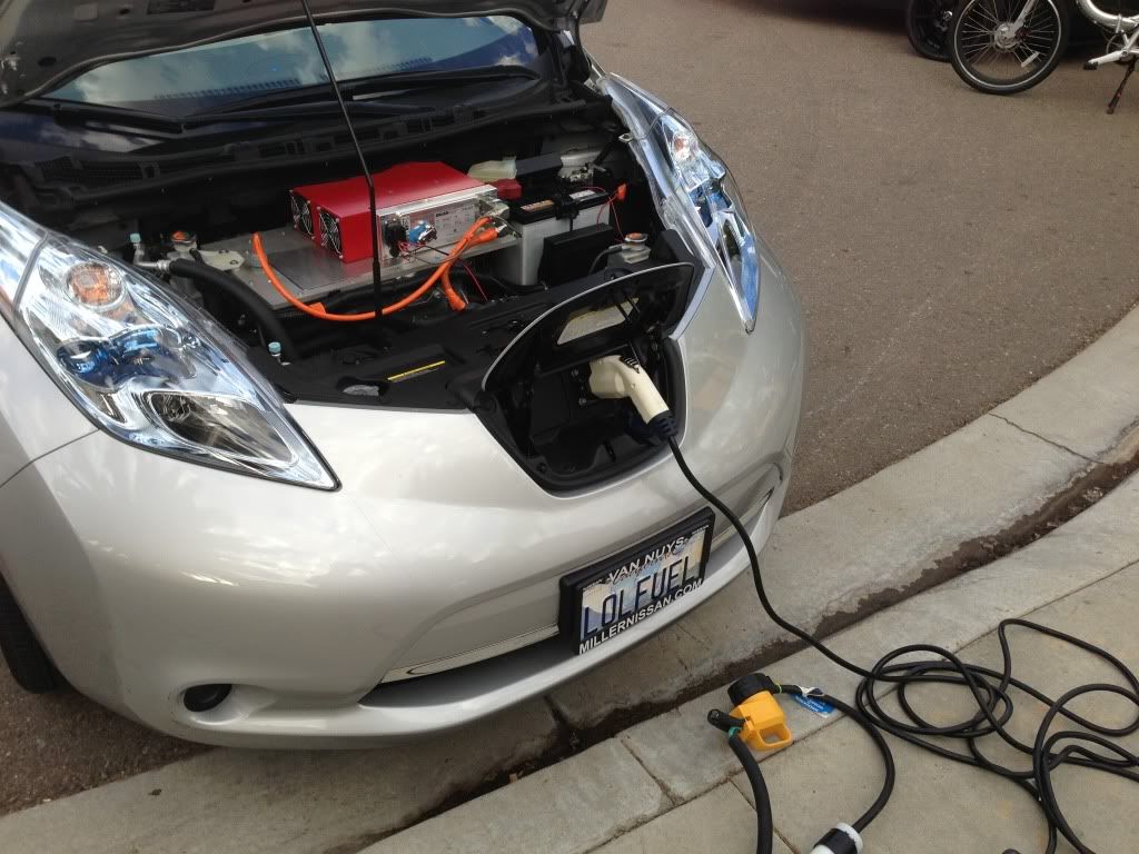
I finally went ahead and finished my Brusa Install.
I have been holding off completing my final installation because the car has been going back to the dealer, trying to get some satisfaction on a recent overnight dramatic loss of 14% of pack capacity, and I didn't want to cloud the issue with this install.
I got nowhere with Nissan, so I figured I might as well proceed with my charger.
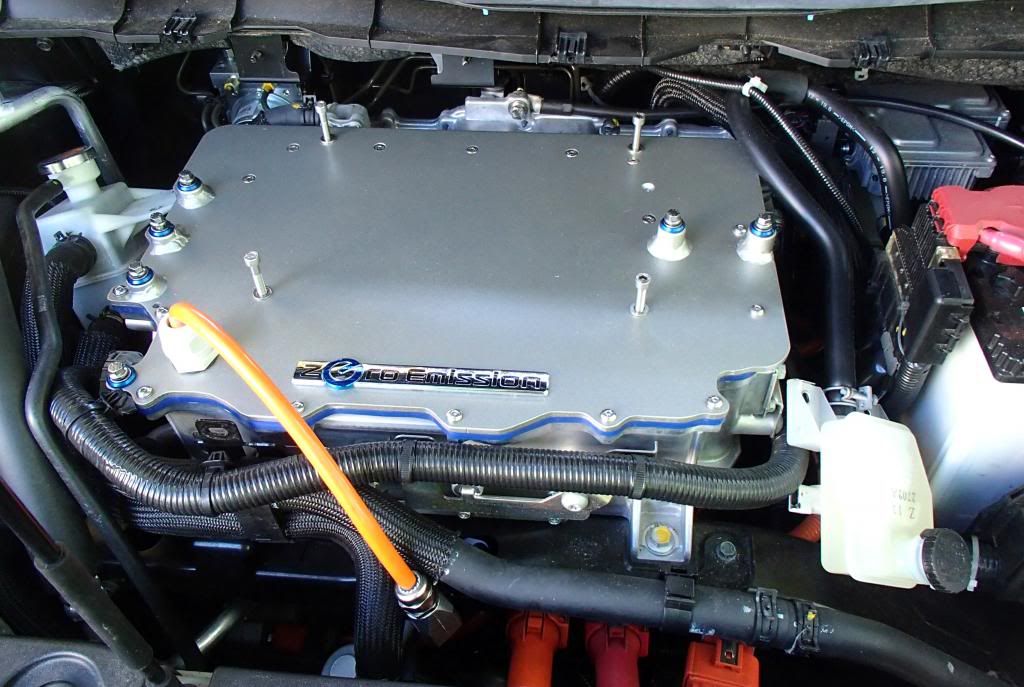
This version is My plan, which I call "plan A", since I built this plate way back in the beginning, but had not yet installed it. My plan was for a more finished OEM look; something that perhaps to an untrained observer, or a Nissan service department , might escape notice, as opposed to the West Coast's more Nimitz Class design ") So, here you go
So, here you go
I pulled everything apart (again) and put away all the OEM stuff for reinstall if need be.
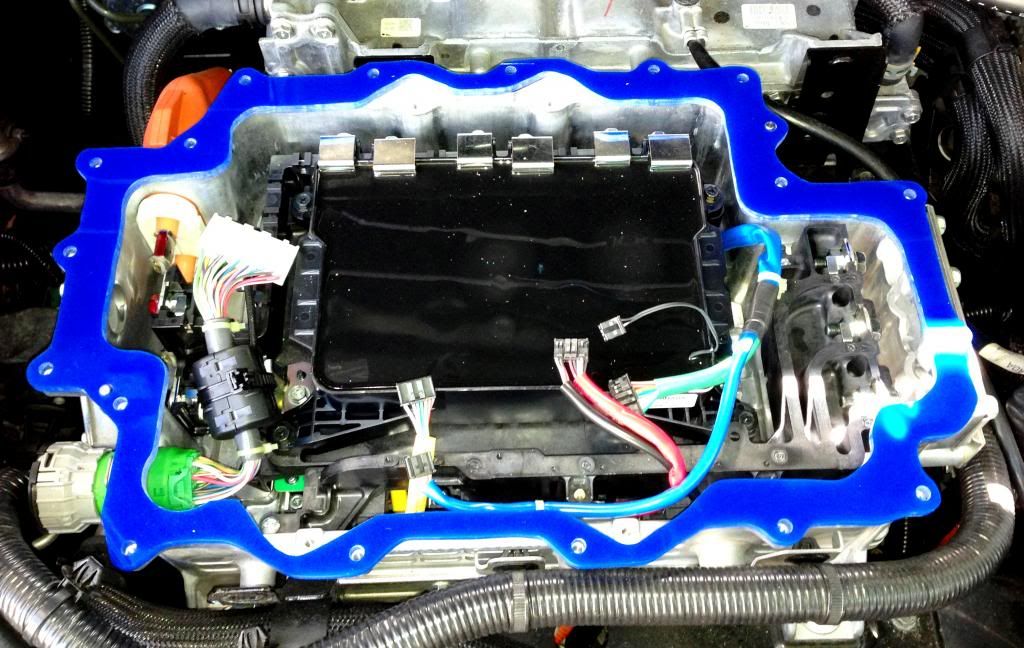
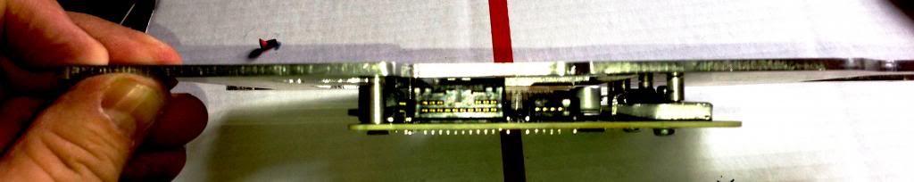
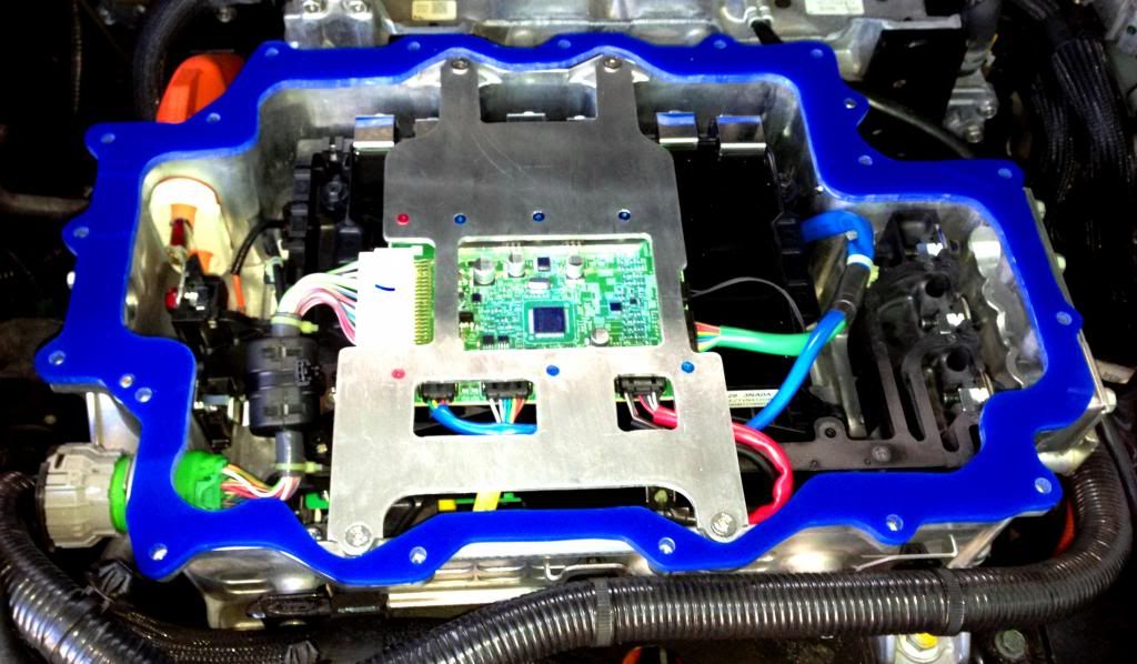
1) As we know, this circuit board assembly (under the “Valve Cover”) comes from Nissan mounted in a way that leaves it “higher” than the plane of the top of the inverter, which interferes with mounting the flat plate. I chose to lower the circuit board assembly. I did it this way so I didn't gain so much height that I couldn't still slide the charger under the rear lip.
I assembled and installed my "Circuit Board Sandwich" used to lower the total height of this assembly to achieve the clearance I needed to mount my plate. I used a bit of blue Thread Locker on the lower screws so that one of them wouldn't wiggle loose at some point and start rattling around in there.
2) I mounted it all up, and found I still needed a "Spacer" between the inverter and my plate. I built this spacer out of Blue translucent Cast HDPE. If I had to do it again, I would probably make it out of Aluminum to maintain shielding. (More on that later)
3) Next comes the mounting plate itself. All the screws that will be covered by the Brusa are countersunk so that it can lie flat. The screws are all 5M, and longer than the originals.
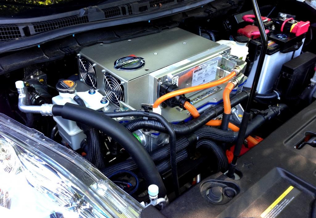
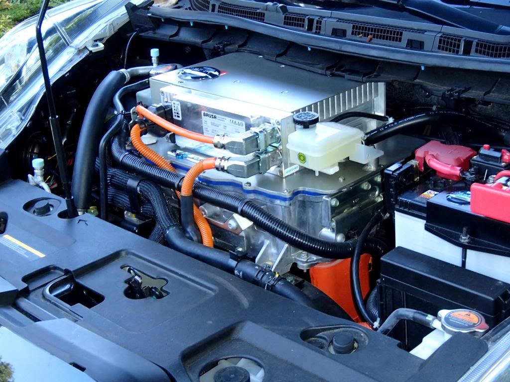
The Brusa output charging harness now consists of simply a positive and negative conductor. The plate was cut, and then clear anodized to harden up the surface, and then Cerakoted to try to replicate the finish found on the OEM "valve cover". I went ahead and duplicated this finish on the actual Brusa cover as well. Side by side it came out spot on for color and texture I think.
I used Screw-Goo (anti seizes) on all the new 5M SS screws so that I wouldn't get any nasty surprises from Aluminum corrosion down the line. The mounting posts are all 3/4" 6061 Rod, welded to the plate, and threaded 6M just like the OEM mountings.
4)
Mounting the Brusa. I wanted to make use of ALL the original screw positions that the original “valve Cover” used. Wanted to Mount from above, so I drilled out the original threaded mounting holes on the Brusa, and threaded the plate instead, so the charger will be secured from the top instead of from below. I used 6M SS Cap head screws because of their small head size being needed to clear the heat fins on the Brusa. I used small spacers between the Brusa and the mounting plate, to try to thermally isolate the two. The guys who are already running their systems have discovered how hot these get, and I don't want that heat coupled directly to my Inverter housing if possible.
So, this is the finished assembly. (The Nissan emblem is just sitting on top; Not sure if I want it there)
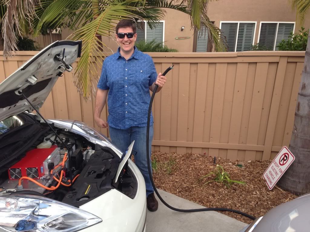
All in all, I'm happy with the result aesthetically, and LOVE the reduced charging time. I can now actually make use of L2 public charging in a meaningful way.
Lessons learned, and things I would do differently;
1) While I tease my very smart West Coast friends about their design (which has a big enough deck to allow flight operations), ultimately their design is probably superior. If I had to start again from scratch, I would retain my top plate design, but leave the circuit board in place as OEM. I would measure out how high I needed to space up my plate to clear the bracket, and cut my gasket / spacer out of aluminum that thickness, more like the California design.
Their design eliminates the fabrication of the Circuit board mount, eliminates the need to mess with the circuit board at all, and when removing the system for Warranty service, they can skip that whole step and simply remove and replace the top cover. If I then needed to get rid of that "clip" that gets in the way of the Brusa; so be it. No big loss.
2) I would have gone with the Water Cooled unit because we have now discovered just how much heat these things need to dissipate. The air cooled works fine, but it gets hot. Also, using the water cooled unit makes quick removal more cumbersome.
3) I would have made my plate 2 inches wider. It's 18" wide. (But with the water cooled unit, I would have gained the additional 2 inches that way.
4) I would NOT have welded the mounting studs to the plate. It turned out to be a real pain, at least for me, because it was really hard to get the 3/4" rod hot enough without melting the 3/16" plate in the process. I would have threaded the whole mounting stud, and used a flat head screw from below to affix it, leaving enough thread protruding up to make it a stud, and use a nut to secure the tanks instead of a bolt.
I'm toying with mounting some pan fans under the hood to try to help with the heat generated.
So it's complete except for adding CAN control later.
My thanks to JeremyW for starting this project.
Thanks to all the guys who discovered all the things that needed discovering, and JasonA for all his encouragement and communication
(and motivational YouTube videos
)